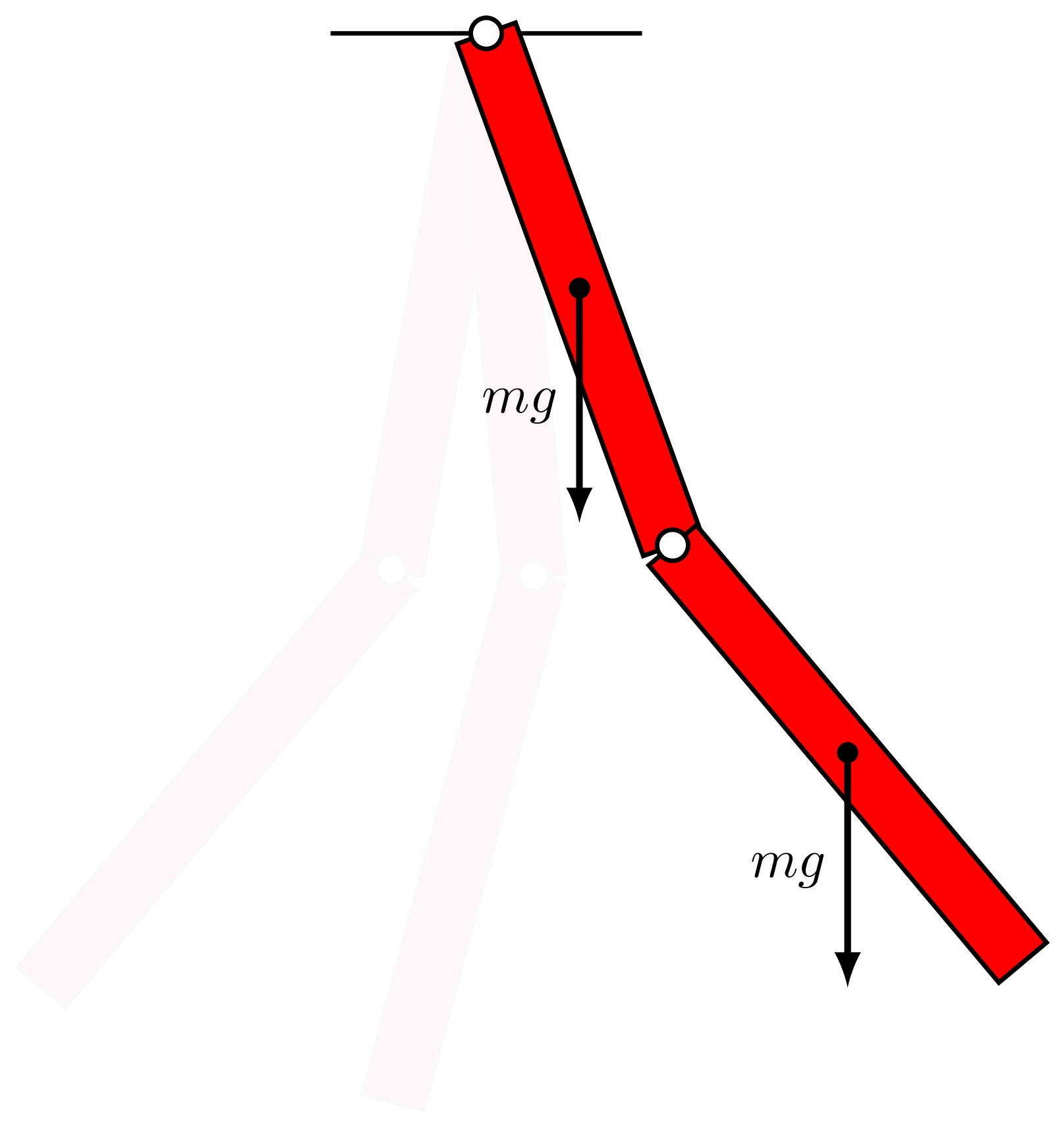
Let's simplify the illustration
Drawing illustration in TikZ can be simplified by a wise choice of the origin (0,0). For rotating parts, we choose the origin as the pivot of the system.
Another interesting point is to draw the double pendulum at the rest position then add a rotation to get the final result.
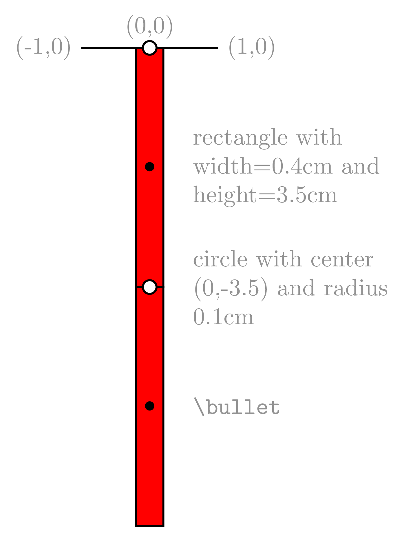
The next illustration presents different parts of the double pendulum in TikZ.
We have:
- Straight line from (-1,0) to (1,0)
- rectangle 1 with 0.4cm width and 3.5cm height. The rectangle corners coordinates are (-0.2cm,0), (0.2cm,0), (-0.2cm,-3.5cm) and (0.2cm,-3.5cm)
- rectangle 2 with 0.4cm width and 3.5cm height. The rectangle corners coordinates are (-0.2cm,-3.5cm), (0.2cm,-3.5cm), (-0.2cm,-7cm) and (0.2cm,-7cm)
- Two small circles that highlight rotation centers of the double pendulum. These circles are filled with white color and have 0.1cm radius. One is positioned at (0,0) and the other at (0,-3.5cm)
- Two small circles filled with black color, which will be used to highlight forces.
Double pendulum in rest position
Here is the LaTeX code of the double pendulum in rest position:
\documentclass[border=0.1cm]{standalone}

\usepackage{tikz}

\begin{document}

\begin{tikzpicture}[thick]

% Straight line
\draw (-1,0) -- (1,0);

% Pendulum part 1 (red rectangle)
\draw[fill=red] (-0.2,0) rectangle (0.2,-3.5)
	node[midway](a){$\bullet$};

% Pendulum part 2 (red rectangle)
\draw[fill=red] (-0.2,-3.5) rectangle (0.2,-7)
	node[midway](b){$\bullet$};

% Two circles filled with white color
\draw[fill=white] (0,-3.5) circle(0.1);
\draw[fill=white] (0,0) circle(0.1);

\end{tikzpicture}

\end{document}
We have added two circles bullets at the middle of each part of the pendulum using node command. The coordinates of these bullets are saved and named by (a) and (b). We will use them later to draw forces.
Now, we need to shake the pendulum to move it from its rest position

Rotate a path around a given point in TikZ
For the double pendulum, we have two rotations: one that corresponds to the top pivot, which affects the two parts of the pendulum, the second corresponds to the bottom part which has to be rotated around the point (0,-3.5cm).
If we have more than draw command, we can regroup them inside a scope environment and add the rotation option to it. Check the code below!
 \documentclass[border=0.1cm]{standalone}

\usepackage{tikz}

\begin{document}
\begin{tikzpicture}[thick]

% Define angles
\newcommand{\angA}{-10}
\newcommand{\angB}{40}

% Straight line
\draw (-1,0) -- (1,0);

\begin{scope}[rotate=\angA]

% Pendulum part 1 (red rectangle)
\draw[fill=red] (-0.2,0) rectangle (0.2,-3.5)
	node[midway](a){$\bullet$};

% Pendulum part 2 (red rectangle)
\draw[fill=red,
	rotate around={\angB:(0,-3.5)}
] (-0.2,-3.5) rectangle (0.2,-7)
	node[midway](b){$\bullet$};

% Two circles filled with white color
\draw[fill=white] (0,-3.5) circle(0.1);
\draw[fill=white] (0,0) circle(0.1);

\end{scope}

\end{tikzpicture}

\end{document}
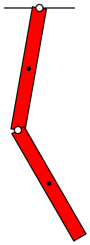
We have created two variables one for the top angle and the second for the bottom one using \newcommand:
% Define angles
\newcommand{\angA}{-10}
\newcommand{\angB}{40}
Free body diagram of double pendulum in TikZ
Now, it remains to add weight forces which are not affected by the pendulum rotation angles. Hence, these forces have to be drawn outside the scope environment. Here is the corresponding code:
 \documentclass[border=0.1cm]{standalone}

\usepackage{tikz}

\begin{document}
\begin{tikzpicture}[thick]

% Define angles
\newcommand{\angA}{20}
\newcommand{\angB}{20}

% Straight line
\draw (-1,0) -- (1,0);

\begin{scope}[rotate=\angA]

% Pendulum part 1 (red rectangle)
\draw[fill=red] (-0.2,0) rectangle (0.2,-3.5)
	node[midway](a){$\bullet$};

% Pendulum part 2 (red rectangle)
\draw[fill=red,
	rotate around={\angB:(0,-3.5)}
] (-0.2,-3.5) rectangle (0.2,-7)
	node[midway](b){$\bullet$};

% Two circles filled with white color
\draw[fill=white] (0,-3.5) circle(0.1);
\draw[fill=white] (0,0) circle(0.1);

\end{scope}

% Weight forces
\draw[-latex,very thick] (a.center) -- ++(0,-1.5)
	node[midway,left]{$mg$};
\draw[-latex,very thick] (b.center) -- ++(0,-1.5)
	node[midway,left]{$mg$};

\end{tikzpicture}

\end{document}
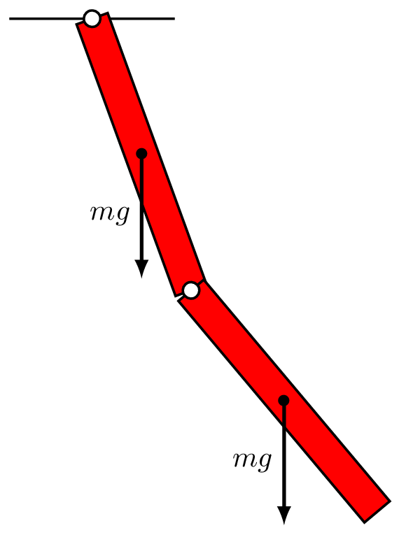
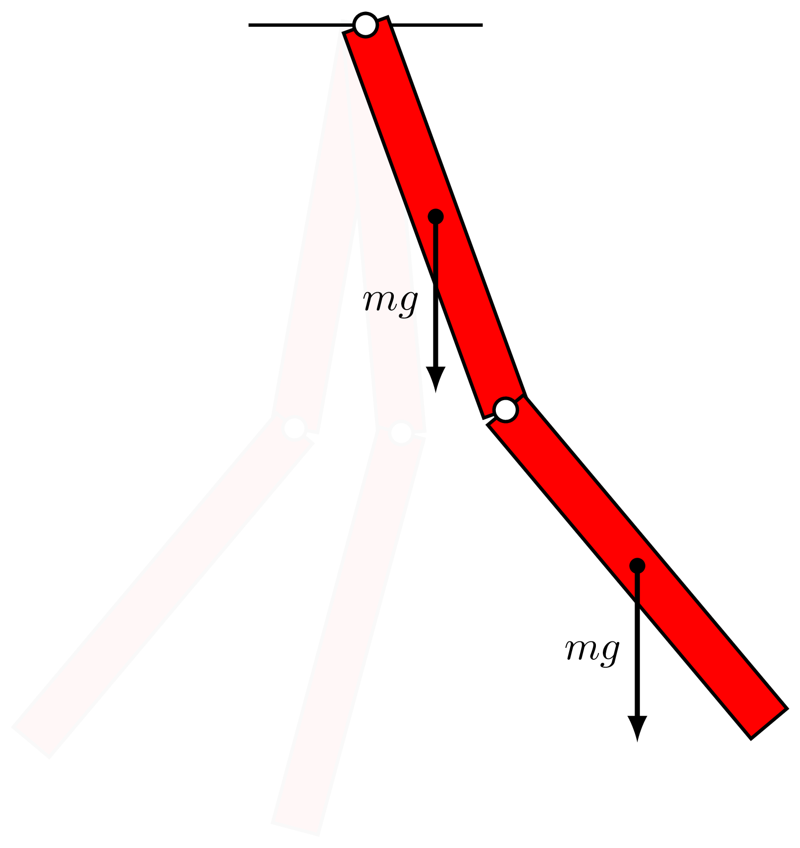
Remark: By copy-past of the scope environment and for different angles' values, we can draw the double pendulum at different positions with a light color.

