
Carnot cycle in TikZ
Let's get into the details!
Step 1: draw axis with labels
Let's start by drawing the axis, for this drawing we will start from 6 cm on the y axis, draw below to the (0,0) coordinate and then go right with 8 cm along the x-axis. We will place two nodes in order to add labels. Here is the corresponding code:
\documentclass [border = .2cm] {standalone}

\usepackage{tikz}

\begin{document}

\begin{tikzpicture}

% Draw axis with labels
\draw [latex-latex] (0,6)  |- (8,0)
	node [pos=.95,below] {Volume}
	node [pos=0.07,above,rotate=90] {Pressure};

\end{tikzpicture}

\end{document}
Comments:
- We have added the option latex-latex in order to add arrowhead on both end of the drawing path. The arrowhead name is latex and for more styles check this post: TikZ arrows.
- We have added pos=<value> to the node command in order to position the label along the drawn path. pos=0 corresponds to the starting point of the path and pos=1 corresponds to the end point of the path.
- We added below option to put the label Volume below the point positioned at 0.95 of the path length.
- We added above option to put the label Pressure above the point positioned at 0.07 of the path length. It's above and not left as we have rotated the node by 90 degrees, flip the screen if you don't believe me  .
.
- We used the operation |- to link the points with coordinates (0,6) and (8,0). It draws a vertical line than a horizonal line. It's different from -| which draws a horizontal line then a vertical line.

Step 2: Add cycle corners
The Carnot cycle corners corresponds to a small circles filled with a black color. Drawing a circle in TikZ can be achieved through methods: 1) using draw command with circle operation, 2) a node command with circle and other options. Check this post for more details: TikZ shapes: Circle
In this example, we will use node command with a circle option (method 2). Here is an updated version of the above LaTeX code:
\documentclass [border = .2cm] {standalone}

\usepackage{tikz}

\begin{document}

\begin{tikzpicture}

% Draw axis with labels
\draw [latex-latex] (0,6)  |- (8,0)
	node [pos=.95,below] {Volume}
	node [pos=0.07,above,rotate=90] {Pressure};

% Cycle corners
\node[circle,
	fill,
	inner sep=1pt,
	label = {left:$1$}] (1) at (2,5){} ;

\node[circle,
	fill,
	inner sep=1pt,
	label = {right:$2$}] (2) at (4.5,4){} ;

\node[circle,
	fill,
	inner sep=1pt,
	label = {right:$3$}] (3) at (5.5,1.5){} ;

\node[circle,
	fill,
	inner sep=1pt,
	label = {below left:$4$}] (4) at (2.5,2.5){} ;

\end{tikzpicture}

\end{document}
Comments:
- We have created nodes at the points with cartesian coordinates: (2,5) for node 1, (4.5,4) for node 2, (5.5,1.5) for node 3 and (2.5,2.5) for node 4.
- nodes are saved with number names (1), (2), (3) and (4). You can choose any names that make sense when you draw your illustration. These names allows us to access to each node coordinates such as its center and any point at its border.
- Each node has a circle a shape and filled by the default color in TikZ (black). The circle size is affected by the node content which is empty in this case. It can be modified by the options: inner separation value (distance from the center of the node to its border) and minimum size of the node. In this example, we have chosen 1pt as an inner separation of each node.
- Node labels are added by providing the option label to the node command. label={above:$1$} will add 1 above the node in question. We can use angles also where label={90:$1$} yields the same result as label={above:$1$}. Again, I deeply invite you to check the post: TikZ shapes: Circle.

\documentclass [border = .2cm] {standalone}

\usepackage{tikz}

\begin{document}

\begin{tikzpicture}
[
	corner/.style={
		circle,
		fill,
		inner sep=1pt}
]

% Draw axis with labels
\draw [latex-latex] (0,6)  |- (8,0)
	node [pos=.95,below] {Volume}
	node [pos=0.07,above,rotate=90] {Pressure};

% Cycle corners
\node[corner,
	label = {left:$1$}] (1) at (2,5){} ;

\node[corner,
	label = {right:$2$}] (2) at (4.5,4){} ;

\node[corner,
	label = {right:$3$}] (3) at (5.5,1.5){} ;

\node[corner,
	label = {below left:$4$}] (4) at (2.5,2.5){} ;

\end{tikzpicture}

\end{document}
Step 3: connect the cycle corners with curved lines
In this step, we will draw curved lines between cycle corners. This can be achieved using bend left or bend right options. To set the bending angle, we can give bend angle as follows: bend left=20 or bend right=30. Here is an example that draws curved lines using bending option with 15 degrees angle:
\draw [blue!70] (1) to [bend right = 15] (2);
\draw [red!70 ] (2) to [bend right = 15] (3);
\draw [blue!70] (3) to [bend left  = 15] (4);
\draw [red!70 ] (4) to [bend left  = 15] (1);
Adding this piece of code to the previous one, we get the following illustration after compilation:

Comments:
- Corner 1 is connected with corner 2 through a curved line using bend right =15. This is intuitive as following the path from corner 1 to corner 2, the bending is on our right hand. If we would like to get the same results but starting from corner 2 to corner 1, then the bending in on our left side.
- Following the path from corner 3 to corner 4, the bending is on our left side.
\documentclass [border = .2cm] {standalone}

\usepackage{tikz}
% For "Arrowhead in a midlle of a line"
\usetikzlibrary{decorations.markings}

\begin{document}

\begin{tikzpicture}
[
% Corner style
	corner/.style={
		circle,
		fill,
		inner sep=1pt},
% Line with Arrow style
	arrowline/.style={
		thick,
		postaction = decorate,
		decoration = {markings,
			mark = at position .6 with \arrow{latex}
		}
	},
]

% Draw axis with labels
\draw [latex-latex] (0,6)  |- (8,0)
	node [pos=.95,below] {Volume}
	node [pos=0.07,above,rotate=90] {Pressure};

% Cycle corners
\node[corner,
	label = {left:$1$}] (1) at (2,5){} ;

\node[corner,
	label = {right:$2$}] (2) at (4.5,4){} ;

\node[corner,
	label = {right:$3$}] (3) at (5.5,1.5){} ;

\node[corner,
	label = {below left:$4$}] (4) at (2.5,2.5){} ;

% Curved lines
\draw [arrowline,blue!70] (1) to [bend right = 15] (2);
\draw [arrowline,red!70 ] (2) to [bend right = 15] (3);
\draw [arrowline,blue!70] (3) to [bend left  = 15] (4);
\draw [arrowline,red!70 ] (4) to [bend left  = 15] (1);

\end{tikzpicture}

\end{document}

Comments:
- We loaded the decorations library using: \usetikzlibrary{decorations.markings}
- We have created a style for the curved lines with an arrowhead at 60% of the path length. The style is named arrowline and used as an option to the previous draw commands.
- The arrowhead style is latex which can be modified as mentioned above (draw axis section).
- The curved line thickness is changed from default to thick which corresponds to 0.8pt.

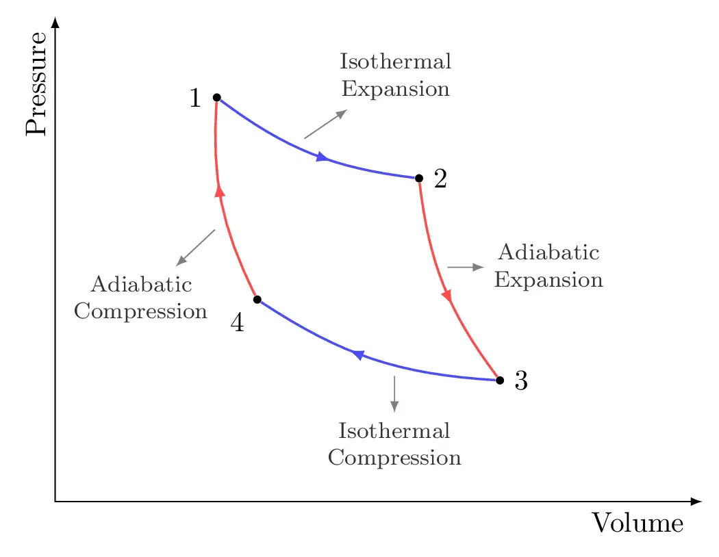
Step 4: add Pins with text
As a final addition, we will add pins to the processes to highlight different stages. This can be achieved thanks to the node option pin. Here is the final version of Carnot cycle that we would like to get:

We will modify the default style of pins in the tikzpicture environment to:
- dark gray pins and labels
- center aligned with a small size font for text nodes
- thin arrow pointing to these labels
- arrowhead of each pin corresponds to latex style
Here is the final LaTeX code of the Carnot cycle:
\documentclass [border = .2cm] {standalone}

\usepackage{tikz}
% For "Arrowhead in a midlle of a line"
\usetikzlibrary{decorations.markings}

\begin{document}

\begin{tikzpicture}
[
% Corner style
	corner/.style={
		circle,
		fill,
		inner sep=1pt},
% Line with Arrow style
	arrowline/.style={
		thick,
		postaction = decorate,
		decoration = {markings,
			mark = at position .6 with \arrow{latex}
		}
	},
% Pin style
	every pin/.style = {
		black!80,
		inner sep = 1mm,
		align = center,
		font = \footnotesize,
		pin edge = {-latex, thin, line to}},
]

% Draw axis with labels
\draw [latex-latex] (0,6)  |- (8,0)
	node [pos=.95,below] {Volume}
	node [pos=0.07,above,rotate=90] {Pressure};

% Cycle corners
\node[corner,
	label = {left:$1$}] (1) at (2,5){} ;

\node[corner,
	label = {right:$2$}] (2) at (4.5,4){} ;

\node[corner,
	label = {right:$3$}] (3) at (5.5,1.5){} ;

\node[corner,
	label = {below left:$4$}] (4) at (2.5,2.5){} ;

% Curved lines
\draw [arrowline,blue!70] (1) to [bend right = 15]
	node [pos = .4, pin = {45:Isothermal\\Expansion}] {} (2);

\draw [arrowline,red!70 ] (2) to [bend right = 15]
	node [pos = .4, pin = {right:Adiabatic\\Expansion}] {}(3);

\draw [arrowline,blue!70] (3) to [bend left  = 15]
	node [pos = .4, pin = {below:Isothermal\\Compression}] {} (4);

\draw [arrowline,red!70 ] (4) to [bend left  = 15]
	node [pos = .4, pin = {260:Adiabatic\\Compression}] {} (1);

\end{tikzpicture}

\end{document}
Comments:
- For each stage, pins are added as nodes positioned at 40% of the path length.
- Labels position follows the same rule as the corners labels.