How to define a variable in LaTeX
In order to make the illustration easy to modify by changing only one parameter that corresponds to the angle θ, we can create a variable for that. This can be achieved in LaTeX using \newcommand as follows:
\newcommand{\ang}{30}
Thus, we will use an angle variable \ang throughout the diagram which will stand for the slope of our inclined plane. In our example, it will be 30 degrees.
Draw a ramp in TikZ
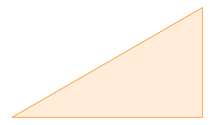
It corresponds to a right triangle which can be easily drawn by three straight lines as follows:
% triangle:
\draw [draw = orange, fill = orange!15] (0,0) coordinate (O) -- (\ang:6)
	coordinate [pos=.45] (M) |- coordinate (B) (O);
We draw the first line that has 6 cm length with a 30 degrees angle, and then finish the line with two perpendicular lines using |- command. While we are drawing the triangle, we will save coordinate along the path to be able to use them after in the code.
- O is for the left corner of the triangle,
- B is for the right corner,
- and we placed M near the middle of our first line to place the load.
Here is the obtained result:
Highlight the ramp angles
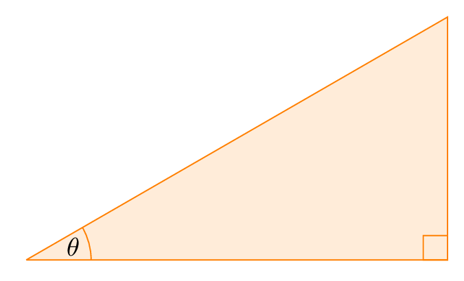
Now, we would like to add labels to the right angle and θ. For the right angle, we'll draw a square of 0.3mm side with right bottom corner on the point B. The angle θ can be highlighted using arc shape, check this post about drawing arcs in TikZ. Here is the corresponding code:
% angles:
\draw [draw = orange] (O) ++(.8,0) arc (0:\ang:0.8)
	node [pos=.4, left] {$\theta$};
\draw [draw = orange] (B) rectangle ++(-0.3,0.3);
Draw the object and add forces
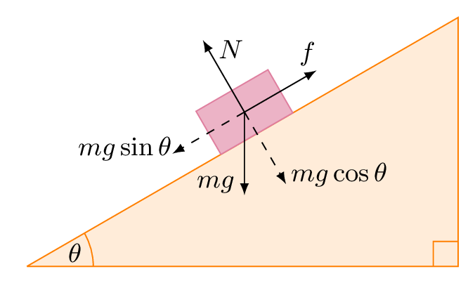
The object is over the inclined surface which means it depends on the angle θ. To this end, we will draw it inside a scope environment on a horizontal line over the point (M). Then, we rotate it by θ:

Here is the corresponding LaTeX code of the inclined plane in TikZ:
\documentclass[border=0.2cm]{standalone}

% Required package
\usepackage{tikz}

\begin{document}

\newcommand{\ang}{30}

\begin{tikzpicture} [font = \small]

% triangle:
\draw [draw = orange, fill = orange!15] (0,0) coordinate (O) -- (\ang:6)
	coordinate [pos=.45] (M) |- coordinate (B) (O);

% angles:
\draw [draw = orange] (O) ++(.8,0) arc (0:\ang:0.8)
	node [pos=.4, left] {$\theta$};
\draw [draw = orange] (B) rectangle ++(-0.3,0.3);

\begin{scope} [-latex,rotate=\ang]

% Object (rectangle)
\draw [fill = purple!30,
	draw = purple!50] (M) rectangle ++ (1,.6);

% Weight Force and its projections
\draw [dashed] (M) ++ (.5,.3) coordinate (MM) -- ++ (0,-1.29)
	node [very near end, right] {$mg\cos{\theta}$};

\draw [dashed] (MM) -- ++ (-0.75,0)
	node [very near end, left] {$mg\sin{\theta}$};

\draw (MM) -- ++ (-\ang-90:1.5)
	node [very near end,below left ] {$mg$};

% Normal Force
\draw (MM) -- ++ (0,1.29)
node [very near end, right] {$N$};

% Frictional Force
\draw (MM) -- ++ (0.75,0)
	node [very near end, above] {$f$};

\end{scope}

\end{tikzpicture}

\end{document}
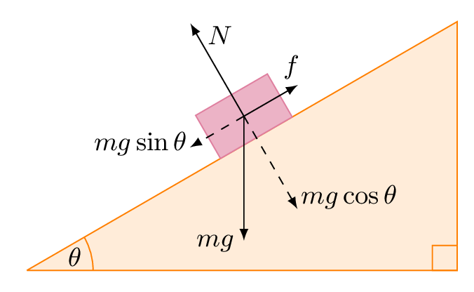
From above, we've drawn different arrows with different lengths, it's just an example and you can adjust it to your case. In this code, the length of each vector is not dependent on the angle. Hence, if you change the angle of the inclined plane, you have to modify each arrow's length. The normal Force has to be equal to the mgcos(θ).
Related Posts
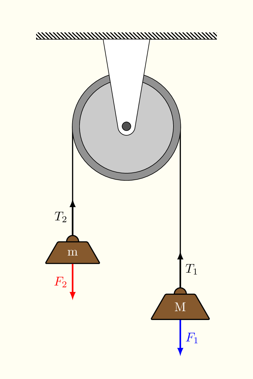
1. Free Body Diagram of Atwood's Machine in TikZ
For more examples about free body diagrams, you can check the gallery of atwood's machine. It corresponds to a step-by-step detailed tutorial.
2. TikZ Free Body Diagram Skydiver with Parachute
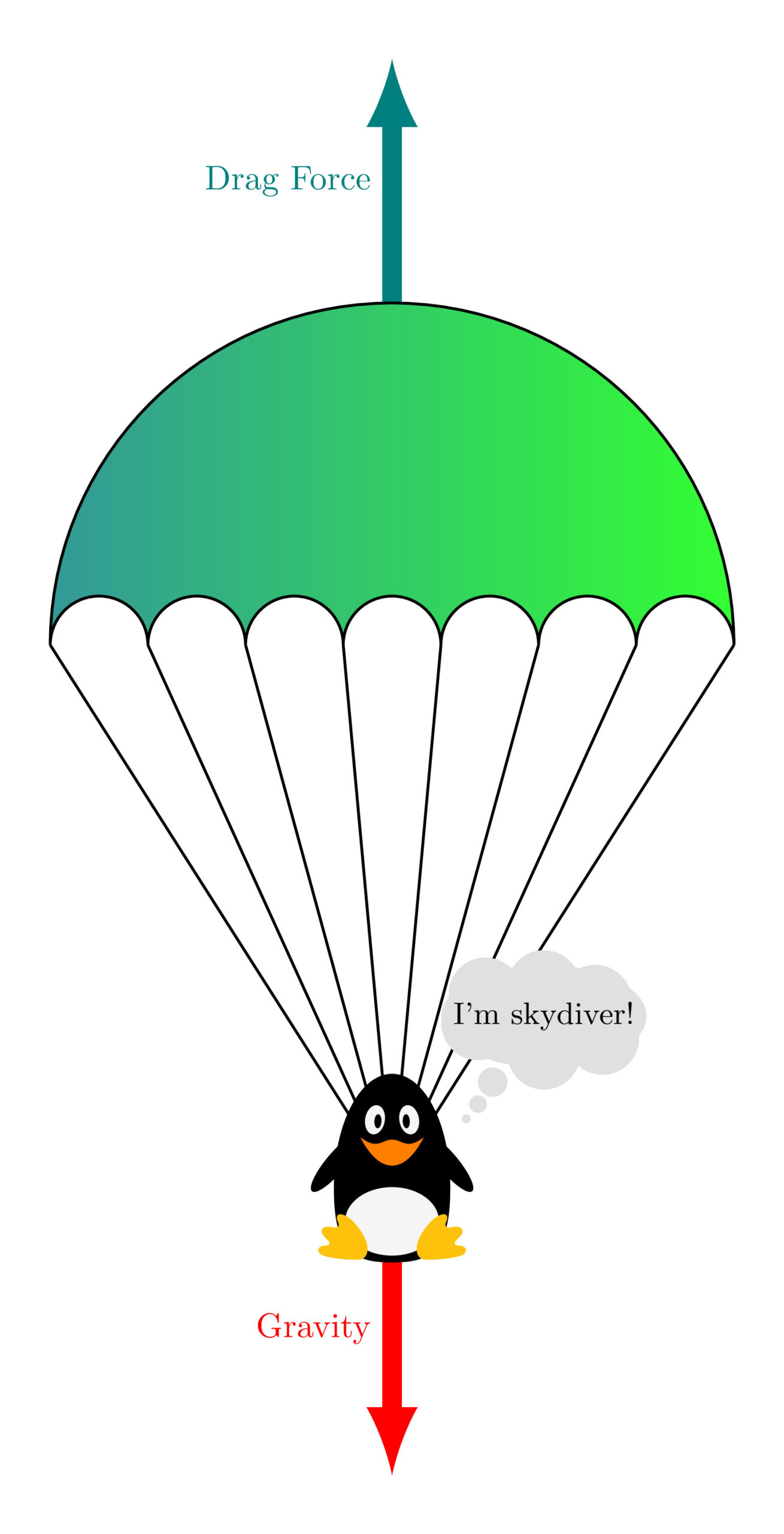
This is a step by step tutorial about drawing the free body diagram of a skydiver with parachute, check the post here!
