What is a Mind Map diagram
Mind map diagrams are used to visually organize information. It has the characteristics of a tree diagram; it has root and child nodes that are connected to its parent in a hierarchical way.
Mind maps are particularly useful for keeping track of brainstorming sessions, taking notes, presenting related ideas more clearly and thinking through complex problems.
Mind map diagram vs tree diagram
The main difference is that in mind maps the root is usually in the center of the page and its child nodes spread out in all directions, instead of going in one direction.
Usually, in a mind map, the root node represents our central concept and the first level of child nodes contains major ideas that are directly connected to the concept. Major ideas are supported or answered by minor ideas, facts and notes.
Drawing a Mind Map in TikZ
Mind map TikZ Library
To get started, we create our drawing environment. We load TikZ package and mindmap library and enter into a tikzpicture environment using mindmap style. Check the following code:
\documentclass{standalone}

% Required package
\usepackage{tikz}
\usetikzlibrary{mindmap}  % Mindmap drawing library

\begin{document}

\begin{tikzpicture}[mindmap]
	% We will draw the mind map here
\end{tikzpicture}

\end{document}
Concept node and concept color
We mentioned the similarities between trees and mind maps. In TikZ, mind maps are formatted on top of tree diagrams. To create our mind map, we will start by creating our root node. Each of our ideas will be branches out of this root.
To create a node, we simply type \node [concept] {our root concept};. We used concept style to indicate that we are drawing the nodes for our mind map concept, so we can make style changes that affect all nodes. One of these styling options is concept color. For our example, let's start with a shade of red.

\begin{tikzpicture}[mindmap, concept color = red!30]

	\node [concept] {Our root concept};

\end{tikzpicture}
Child nodes styling
Next thing to do is to give our root node some child nodes to branch out. We can easily do that using child keyword. In each child, we will create another node in a recursive way. Syntax for the child nodes will not include backslashes:
child {node {node content}}
These child nodes will also need to be elements affected by the concept style. To avoid repetition, we can tell the environment to change every node to make them concept nodes by adding every node/.style = {concept} command in the styling of our tikzpicture. Then we can erase the style option in our root node, as we no longer need it.
\begin{tikzpicture}
[
	mindmap,
	concept color = red!30,
	every node/.style = {concept}
]

\node {Our root concept} child
{
	node {First idea}
};

\end{tikzpicture}

Position child nodes using Grow key
As we add new child nodes to our mind map, we will need to think about their position. We can give them a specific position using grow option. This way, we will have the freedom to place them as we please. We can use a set of keywords (up, down, left, right, north, south, east, west, north east, etc) or angles with the grow option. To see some of these options, let's add some child nodes to our root.
\begin{tikzpicture}
[
	mindmap,
	concept color = red!30,
	every node/.style = {concept}
]

\node  {Our root concept}
	child [grow = down] {
		node {First idea}
			child [grow = left] {node {Fact 1}}
			child [grow = right] {node {Fact 2}}
	}
	child [grow = north west] {
		node {Second idea}
			child [grow = 30] {node {Sub-idea}}
};

\end{tikzpicture}

Circular grow option
Although we have this option, we can handle growing much more easily by using grow cyclic option in our TikZ environment. This option will grow the tree in a circular fashion and keep our root concept at the center. We need to remove other grow commands to see its effects (check the next code).
Styling different levels of mind map diagram
Next, we'll go over the options to style different levels of our nodes. TikZ mindmap library gives us the option to style five different levels of our mind map diagram:
root concept, level 1, level 2, level 3 and level 4.
There are no options for level 5+. Level 1 nodes are children of our root concept, level 2 nodes are children of the level 1 nodes, and so on. We can alter styling options such as concept color, level distance or angle distance for each sibling node by using append style. Following code shows different options in practice with couple more child nodes.
\begin{tikzpicture}[
	mindmap,
	concept color = red!30,
	every node/.style = {concept},
	grow cyclic,
	level 1/.append style = {
		concept color = red!20,
		level distance = 4.5cm,
		sibling angle = 120
	},
	level 2/.append style = {
		concept color = red!10,
		level distance = 3cm,
		sibling angle = 45
	}
]

\node  {Our root concept}
	child {node {First idea}
		child {node {Fact 1}}
		child {node {Fact 2}}
	}
	child {node {Second idea}
		child {node {Sub-idea}}
	}
	child {node {Third idea}
		child {node {Note 1}}
		child {node {Note 2}}
		child {node {Note 3}}
};

\end{tikzpicture}
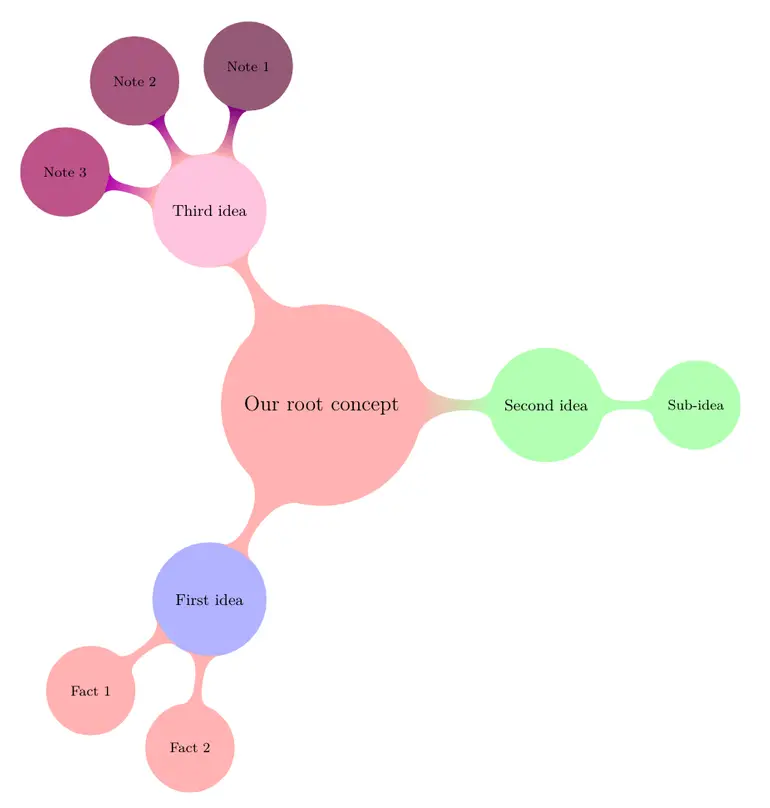
Which yields the following mind map diagram

In our example, we were able to choose a lighter concept color tone for each level. Another change was implemented with level distance command. Level distance represents the distance between center of the parent node and center of the child node.
In our case, our first level distance is 4.5 cm and second level distance is 3 cm. We also put a rotational distance between sibling nodes in a level; for level 1 nodes it is 120 degrees and for level 2 nodes it is 45 degrees. For the first level, rule of thumb is having the sibling angle at 360 degrees count; this option would fit each node in a circular way around the root node.
Colorize nodes differently
Another way to colorize the nodes is to give each level 1 idea its own color. To achieve that, we can add different concept color option to each of our level 1 nodes instead of setting a generic rule for all the nodes in the level. Our code below tries different options of coloring the child nodes. Notice that we erased the concept color part from the level 1 and 2 styles.
\begin{tikzpicture}[
	mindmap,
	concept color = red!30,
	every node/.style = {concept},
	grow cyclic,
	level 1/.append style = {
		level distance = 4.5cm,
		sibling angle = 120
	},
	level 2/.append style = {
		level distance = 3cm,
		sibling angle = 45}
]

\node {Our root concept}
	child {node [concept color = blue!30] {First idea}
		child {node {Fact 1}}
		child {node {Fact 2}}
	}
	child [concept color = green!30] {node {Second idea}
		child {node {Sub-idea}}
	}
	child {node [concept color = magenta!30] {Third idea}
			child [concept color = magenta!50!black] {node {Note 1}}
			child [concept color = magenta!60!black] {node {Note 2}}
			child [concept color = magenta!70!black] {node {Note 3}}
	};

\end{tikzpicture}

In our first child node, we changed the styling of the node inside our child command, which only changed level 1 and didn't change level 2. In our second child node, we changed the styling of the child command, which changed all of its child nodes too. Finally, in our third child node, we give each of the nodes a different color. You can change each node's color using these options. Notice that when we changed the color of the child command, there is a transition between colors which is not there when we changed the color of just the node or the whole level.
Add connections to a Mind Map diagram in LaTeX
In a mind map, sometimes nodes belonging to other parents might have connections between each other. We have the option to represent these connections using TikZ. The easiest way to connect two nodes is to draw a line between them. mindmap library has concept connection option to handle these type of connections.
To connect our nodes, first we must give them names by adding their names in parentheses between node style and content, then call draw function with these names using concept connection option. To keep the names easy and short, I named the root concept root and used numbers for each level and node. For example name of 'First idea' is 1, 'Fact 1' is 11 and 'Fact 2' is 12.
Then we will call our draw function. Let's say there is a connection between Fact 1 of First idea and Note 3 of Third idea. The line will move in empty space and will not overlap with any node. However, if we try to connect Fact 2 of First idea with Note 1 of Third idea, our line will go over both First idea and Third idea nodes and make them harder to read. To solve this issue, we can draw our lines in a background layer.
Background Layer in TikZ
To use backgrounds, we need to add backgrounds library, which will enable pgfonlayer command. We can make the connection more visible if we draw the line from north east of Fact 2 to south east of Note 1. In the following code all nodes are named and connections between nodes are drawn in a background layer. Additionally, we added a styling option to make our connection lines blue.
\documentclass{standalone}

% Required package
\usepackage{tikz}
\usetikzlibrary{mindmap, backgrounds}

\begin{document}

\begin{tikzpicture}[
	mindmap,
	concept color = red!30,
	every node/.style = {concept},
	grow cyclic,
	level 1/.append style = {
		level distance = 4.5cm,
		sibling angle = 120
	},
	level 2/.append style = {
		level distance = 3cm,
		sibling angle = 45
	},
	concept connection./append style = {
		color = blue!70
	}
]

\node (root) {Our root concept}
	child {node [concept color = blue!30] (1) {First idea}
		child {node (11) {Fact 1}}
		child {node (12) {Fact 2}}
	}
	child [concept color = green!30] {node (2) {Second idea}
		child {node (21) {Sub-idea}}
	}
	child {node [concept color = magenta!30] (3) {Third idea}
			child [concept color = magenta!50!black] {node (31) {Note 1}}
			child [concept color = magenta!60!black] {node (32) {Note 2}}
			child [concept color = magenta!70!black] {node (33) {Note 3}}
	};

\begin{pgfonlayer}{background}
\draw [concept connection]
	(11) edge (33)
	(12.north east) edge (31.south east);
\end{pgfonlayer}

\end{tikzpicture}

\end{document}

Annotate a Mind Map diagram in LaTeX
mindmap library of TikZ also gives us the option to insert annotations inside our diagram. We can style them using annotation keyword and insert them to the diagram using the positions of our nodes. Using calc library, we can position our annotations freely. Following code shows two annotation nodes in the diagram.
\documentclass{standalone}

% Required package
\usepackage{tikz}
\usetikzlibrary{mindmap, backgrounds, calc}

\begin{document}

\begin{tikzpicture}[
	mindmap,
	concept color = red!30,
	every node/.style = {concept},
	grow cyclic,
	level 1/.append style = {
		level distance = 4.5cm,
		sibling angle = 120
	},
	level 2/.append style = {
		level distance = 3cm,
		sibling angle = 45
	},
	concept connection./append style = {
		color = blue!70
	},
	every annotation/.append style = {
		fill = yellow!20,
		text width = 2cm
	}
]

\node (root) {Our root concept}
	child {node [concept color = blue!30] (1) {First idea}
		child {node (11) {Fact 1}}
		child {node (12) {Fact 2}}
	}
	child [concept color = green!30] {node (2) {Second idea}
		child {node (21) {Sub-idea}}
	}
	child {node [concept color = magenta!30] (3) {Third idea}
			child [concept color = magenta!50!black] {node (31) {Note 1}}
			child [concept color = magenta!60!black] {node (32) {Note 2}}
			child [concept color = magenta!70!black] {node (33) {Note 3}}
	};

\begin{pgfonlayer}{background}
\draw [concept connection]
	(11) edge (33)
	(12.north east) edge (31.south east);
\end{pgfonlayer}

\node[annotation] at ($(2.north) + (0,0.5)$)
{
	Need to work more on our second idea
};

\node[annotation] at ($(root.south east) + (.5,-.5)$)
{
	Our root concept is still just an abstraction!
};

\end{tikzpicture}

\end{document}

Let's analyze our additions. First we set the color and text width of our annotation nodes. Then we added the nodes, but while inserting, we used a calculation on the coordinate system to position them.
($(2.north) + (0,0.5)$) means adding 0.5 on y axis to the position of the upper end of our Second idea node.
Our second annotation uses a similar calculation—($(root.south east) + (.5,-.5)$), it is placed 0,5 unit right and 0,5 unit down of the south east end of the root concept node.
Add Extra Isolated Node
Another option that mindmap library gives us is for creating some extra concepts, which are not connected with our root concepts. We can insert these nodes using extra concept keyword and position them using the relative positioning system we discussed. Let's create an extra concept node which has a black background and bold, white text, positioned at far south east of our root node.
\documentclass{standalone}

% Required package
\usepackage{tikz}
\usetikzlibrary{mindmap, backgrounds, calc}

\begin{document}

\begin{tikzpicture}[
	mindmap,
	concept color = red!30,
	every node/.style = {concept},
	grow cyclic,
	level 1/.append style = {
		level distance = 4.5cm,
		sibling angle = 120
	},
	level 2/.append style = {
		level distance = 3cm,
		sibling angle = 45
	},
	concept connection/.append style = {
		color = blue!70
	},
	every annotation/.append style = {
		fill = yellow!20,
		text width = 2cm
	},
	every extra concept/.append style = {
		text = white,
		font = \bfseries,
		concept color = black!80
	}
]

\node (root) {Our root concept}
	child {node [concept color = blue!30] (1) {First idea}
		child {node (11) {Fact 1}}
		child {node (12) {Fact 2}}
	}
	child [concept color = green!30] {node (2) {Second idea}
		child {node (21) {Sub-idea}}
	}
	child {node [concept color = magenta!30] (3) {Third idea}
			child [concept color = magenta!50!black] {node (31) {Note 1}}
			child [concept color = magenta!60!black] {node (32) {Note 2}}
			child [concept color = magenta!70!black] {node (33) {Note 3}}
	};

\begin{pgfonlayer}{background}
\draw [concept connection]
	(11) edge (33)
	(12.north east) edge (31.south east);
\end{pgfonlayer}

\node[annotation] at ($(2.north) + (0,0.5)$)
{
	Need to work more on our second idea
};
\node[annotation] at ($(root.south east) + (.5,-.5)$)
{
	Our root concept is still just an abstraction!
};

\node[extra concept] at ($(root.south east) + (2,-4)$)
{
	Another idea to consider
};

\end{tikzpicture}

\end{document}
