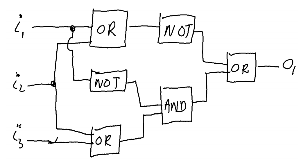
Hand drawn circuit suggested by Nithin Aaron
Short description
LaTeX code of the Logic circuit: IEEE style
 \documentclass[border=0.2cm]{standalone}

% Required packages and libraries
\usepackage{circuitikz}
\usetikzlibrary{calc}

\begin{document}


\begin{tikzpicture}

% Circuit style
\ctikzset{
	logic ports=ieee,
	logic ports/scale=0.8,
	logic ports/fill=lightgray
}

% Logic ports
\node[or port] (ORa) at (0,0){};
\node[not port] (Noa) at (0,-2){};
\node[or port] (ORb) at (0,-4){};

\node[not port] (Nob) at (2.5,0){};
\node[and port] (ANDa) at (2.5,-3){};

\node[or port] (ORc) at (5,-1.5){};

% Connection
\draw (ORa.out) -- (Nob.in);

\draw (Noa.out) -| (ANDa.in 1);
\draw (ORb.out) -| (ANDa.in 2);

\draw (ANDa.out) -|  (ORc.in 2);
\draw (Nob.out) -| (ORc.in 1);
\draw (ORc.out) -- ++(1,0) node[near end,above]{Out};

\draw (ORa.in 1) -- ++(-1.5,0)node[left](In1){In1};
\draw (ORb.in 2) -- ++(-1.5,0)node[left](In3){In3};

% Jump crossing element
\node at (ORa.in 2)
[
	below,
	jump crossing,
	rotate=-90,
	scale=1.3
](X){};

\draw (Noa.in) -| (X.east)
	(X.west) to[short,-*] (X.west |- ORa.in 1);

\draw ($ (In1) !.5! (In3) $) node[]{In2}
	++ (0.4,0) to[short,-*] ++(0.5,0) coordinate(a)
	|- (X.south) (a) |- (ORb.in 1);
\end{tikzpicture}


\end{document}
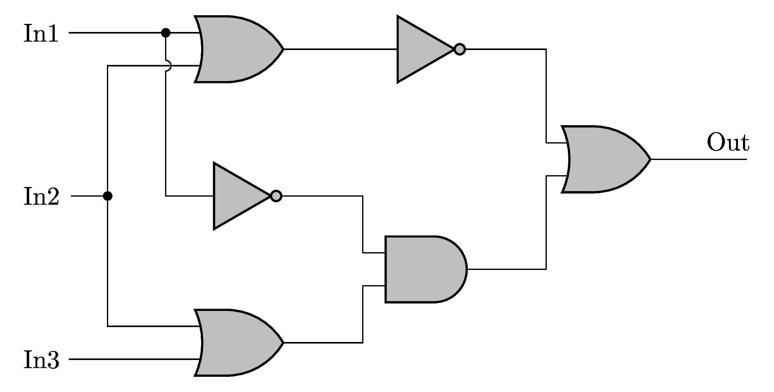
Compiling the above code yields:

Logic Circuit in CircuitikZ with IEEE components style
LaTeX code of the Logic circuit: American style
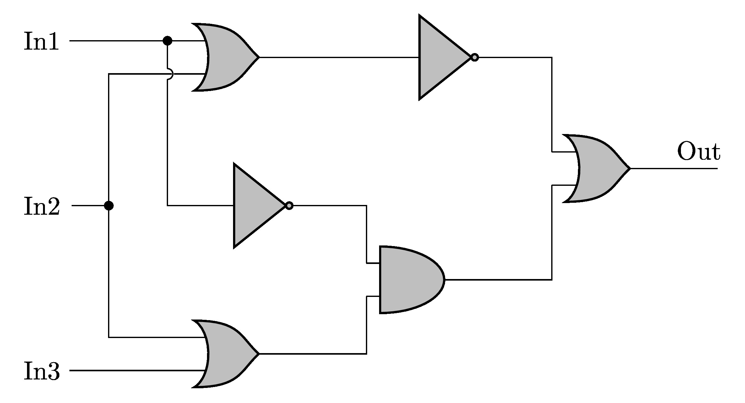
By changing the style from ieee to american in the above code, we will get:

Logic Circuit in CircuitikZ with American components style
LaTeX code of the Logic circuit: European style
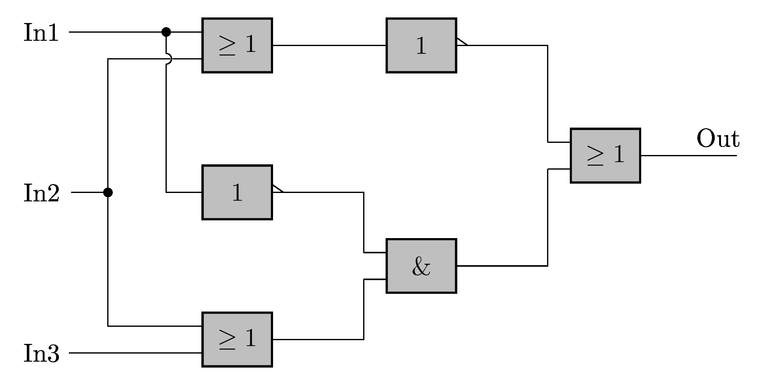
By changing the style from ieee to european in the above code, we will get:

Logic Circuit in CircuitikZ with European components style


It’s not the scope of this site, but did you try to figure out the logical behaviour of that thing?
SPOILER
It’s just an inverter for i₁.
Hey Moss!
That’s correct, and here is a detailed answer for future curious minds:
Let’s consider the algebraic notation:
+ for OR gate, * for AND gate, ! for NOT gate.
We have:
!(a + b) + (!a * (b + c))!a * !b + !a * b + !a * c
!a * (!b + b) + !a * c
It should be noted that !b + b is always true. Therefore, this is equal to:
!a + !a * cBut the right side being true implies the left side is also true. Therefore, we can say it’s just:
!aSource: Bassel Toubbeh from “It’s in LaTeX so it must be true” facebook group.