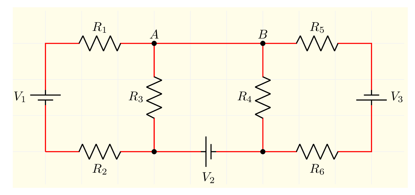
- This post is about drawing a simple circuit in LaTeX using CircuiTikZ package. It consists of resistors and voltage sources connected in series and in parallel.
Short description
- The circuit consists of labelled resistors and voltage sources. Both components can be drawn along the path (not as a node, check this post for more details). Labels of points A, B are added using the node command. Check the code below!
LaTeX code of the circuit
\documentclass[border=0.2cm]{standalone}

% Package
\usepackage{circuitikz}

% Change thickness of bipoles
\ctikzset{bipoles/thickness=1}

\begin{document}

\begin{circuitikz}[line width=0.8pt,draw=red]

% Yellow box and grid
\fill [yellow!10](-0.9,-1) rectangle (10,4);
\draw [gray!10,thin](-0.9,-0.9) grid (9.9,3.9);

% Circuit code
\draw (0,0) to [battery1,invert,l=$V_1$] (0,3)
	to [R,l=$R_1$] (3,3) node[above]{$A$}
	to (6,3) node[above]{$B$}
	to [R,l=$R_5$] (9,3)
	to[battery1,invert,l=$V_3$] (9,0)
	to [R,l=$R_6$] (6,0)
	to [battery1,l=$V_2$,invert] (3,0)
	to [R,l=$R_2$] (0,0);

% Intermediate resistors
\draw (3,0) to[R,l=$R_3$,*-*] (3,3);
\draw (6,0) to[R,l=$R_4$,*-*] (6,3);

\end{circuitikz}

\end{document}- If you would to write a detailed tutorial about it, leave me a comment below or reach me via e-mail at admin@latexdraw.com, I will be happy to hear from you!

