In this tutorial, we will learn how to draw a dc-dc buck converter in LaTeX using CircuiTikZ package.
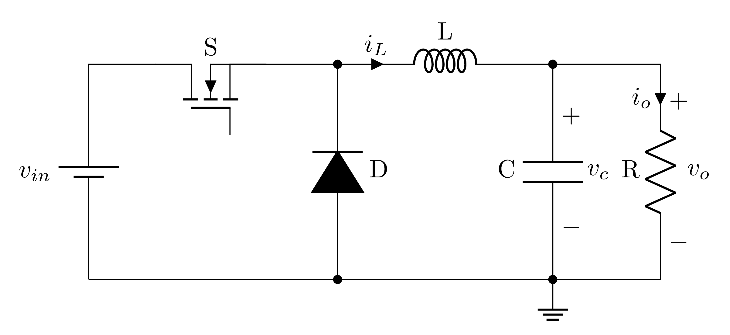
The idea is to recreate the circuit diagram shown in Fig. 1, which is published recently in IEEE Xplore.
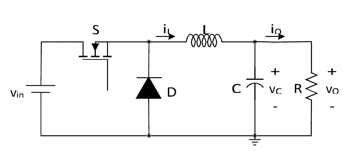
Buck converter circuit diagram (published in IEEE Xplore 2019)
What motivates me to use TikZ
Some of the drawbacks of adding an image directly into a LaTeX document are:
- The font is not the same as the rest of the document,
- The font size is affected when the image is scaled,
- If you would like to modify your illustration you have to go back to the used drawing tool, more distraction.
Well, we assume that the image in question is a good one, like mine 
For that, I prefer to use TikZ to draw my illustrations and benefit from its features such as precision, reusability and automation. And when it comes to drawing circuits in LaTeX, circuitikz is the best option.
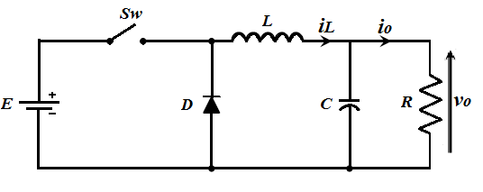
My first illustration, December 2011.
CircuiTikZ, minimal code
The CircuiTikZ package can be loaded as follows:
 \documentclass[border=0.2cm]{standalone}

\usepackage{circuitikz}

\begin{document}

\begin{circuitikz}[american]
	% Put your code here!
\end{circuitikz}

\end{document}
The circuit code will be added inside the CircuiTikZ environment which is an alias for tikzpicture. As an option, we have chosen american style for the electrical components.
The Origin, a successful journey depends on it!
Choosing the starting point of your illustration (the origin) is important as it makes positioning easy to deduce. Sometimes, to go faster, I draw my illustration down in a paper and add coordinates to it. The latter are adjusted later by trial and error method until I get a satisfactory result. Here is my hand drawn version of a dc-dc buck converter:
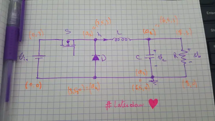
Hand drawn version of a dc-dc buck converter
I have chosen the starting point at the bottom left of the circuit diagram. From there, I will draw a dc source then 


Along this path, I save coordinates to use them later to draw the diode and the capacitor (a1 and a2). Ready for details, Let's go!
DC/DC buck converter circuit diagram
Before going further with details and for curious minds, Here is the buck converter schematic drawn in LaTeX using the CircuiTikZ package:
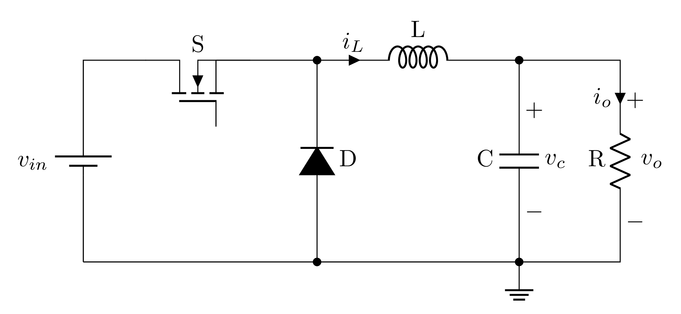
DC-DC Buck converter drawn in LaTeX using CircuiTikZ package
And the corresponding code is:
 \documentclass[border=0.2cm]{standalone}
\usepackage{circuitikz}

\begin{document}

\begin{circuitikz}[american]

% Change components size
\ctikzset{
	resistors/scale=0.7,
	capacitors/scale=0.7,
	diodes/scale=0.7,
	inductors/coils=6
}

% Add switch
\node[nigfete,rotate=90,label=S] (switch)at (1.7,3){} ;

% Draw DC source
\draw (0,0) to[battery1,invert,l=$v_{in}$] ++(0,3) -- (switch.D);

% Draw the inductor
\draw (switch.E) -- ++(1,0) coordinate(a1);

\draw (a1) to[cute inductor,l=L, i>^=$i_L$]
++(3,0) coordinate(a2);

% Draw the resistor
\draw (a2) -- ++(1.5,0)
	to[R,l_=R,v^>=$\:v_o$,i">"_=$i_o$] ++(0,-3)
	to[short] ++(-1.5,0) coordinate(a3);

% draw the ground
\node[ground] at (a3) {};

% Close the circuit
\draw (a3) -- ++(-3,0) coordinate(a4);
\draw (a4) -- (0,0);

% Draw the capacitor
\draw (a3) to[C,invert,*-*,l=C,v<=$\:v_c$] (a2);

% Draw the diode
\draw (a4) to[D*,l_= D,*-*] (a1);

\end{circuitikz}

\end{document}
Let's start drawing our circuit from scratch!
Step 1: Add a transistor as a node
From the CircuiTikZ manual, the transistor type is named nigfete which can be added using node command at any coordinate. It has four predefined connectors as shown in the next illustration where we can link paths to it.
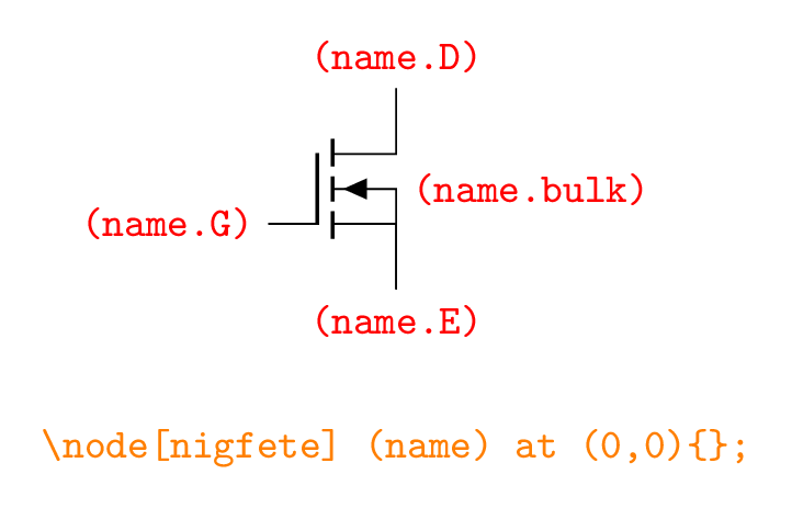
Transistor anchors
In the circuit code, we have added the transistor as a node at the point with coordinates (1.7,3) and we named it (switch) to get access to its four connectors. This corresponds to line (17) of the code:
\node[nigfete,rotate=90,label=S] (switch)at (1.7,3){} ;
By default, the transistor orientation is shown above and to get the right one, we have rotated it by 90 degrees using the option rotate=90. In addition, the switch has a label S, which is set by the option label=S.
Step 2: Draw dc voltage source
From the CircuiTikZ manual, the dc voltage source corresponds to the element with the name battery1 which belongs to the first components category. Thus, it will be placed along a path. It is drawn from the origin to the point (0,3) and then linked to the transistor through its connector (switch.D):
\draw (0,0) to[battery1,invert,l=$v_{in}$] ++(0,3) -- (switch.D);

Inverting the DC voltage source polarity
The DC voltage source has the label [latex]v_{in}[/latex], which is defined by the option l=$v_{in}$. We can specify the label position (right or left of the electrical component) using l^=$v_{in}$ or l_=$v_{in}$.
Step 3: Draw an inductor
Now, we have to move from the right of the transistor (switch.E) by 1cm along the x-axis and save the coordinate using the command coordinate as follows:
\draw (switch.E) -- ++(1,0) coordinate(a1);
\draw (a1) to[cute inductor,l=L,i>^=$i_L$] ++(3,0) coordinate(a2);
The inductor shape is obtained using the option (cute inductor). With the same manner as the DC voltage source, we have added the label L to the inductor using the option l=L

Inductor styles L vs cute inductor
Inductor current is draw at its input where direction and label position can be specified as follows:
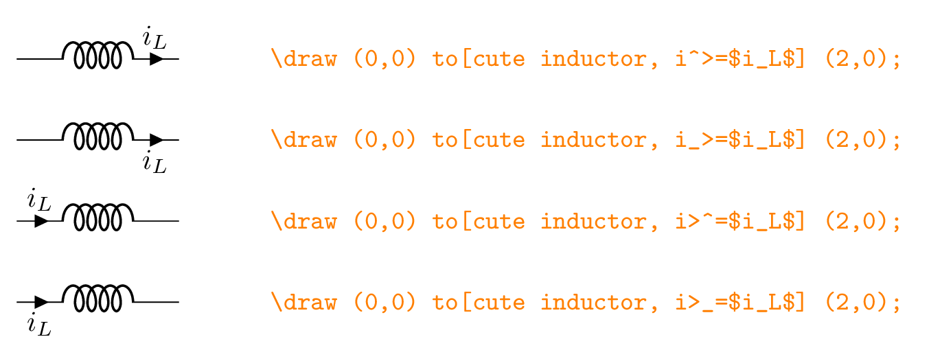
Current arrow and label positions (left to right direction).
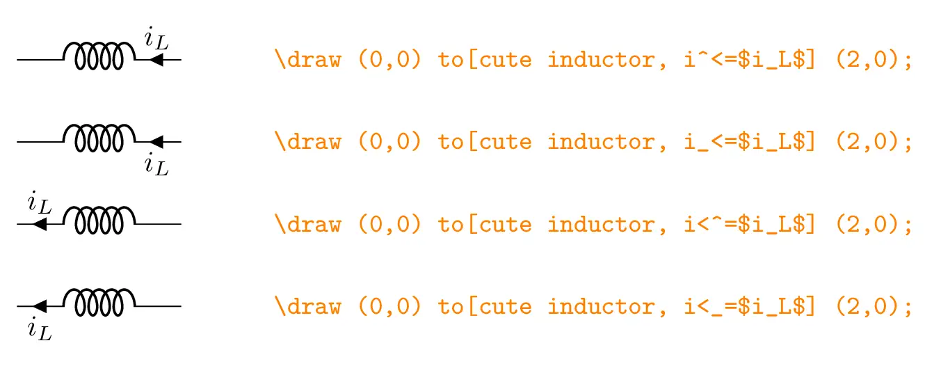
Current arrow and label positions (right to left direction).
Step 4: Draw a resistor
From the point (a2), we draw a straight line along the x-axis and from there we draw a resistor (using the option resistor or simply R ) along the y-axis as follows:
\draw (a2) -- ++(1.5,0) to[R,l_=R,v^>=$v_o$,i>_=$i_o$] ++(0,-3) -- ++(-1.5,0) coordinate(a3);
Step 4: Add a ground
The ground is added as a node at the point named (a3):
\node[ground] at (a3) {};

Ground added as a node in two cases: with and without rotation
From the point (a3), we have drawn a straight line to the origin and we have saved the point (a4) to be used later to draw the diode:
\draw (a3) -- ++(-3,0) coordinate(a4);
\draw (a4) -- (0,0);
Step 5: Draw a capacitor and a diode
Now, we draw the diode between the points (a1) and (a4), and the capacitor between the points (a2) and (a3) :
\draw (a3) to[C,invert,*-*,l=C,v<=$\:v_c$] (a2);
\draw (a4) to[D*,l_= D,*-*] (a1);
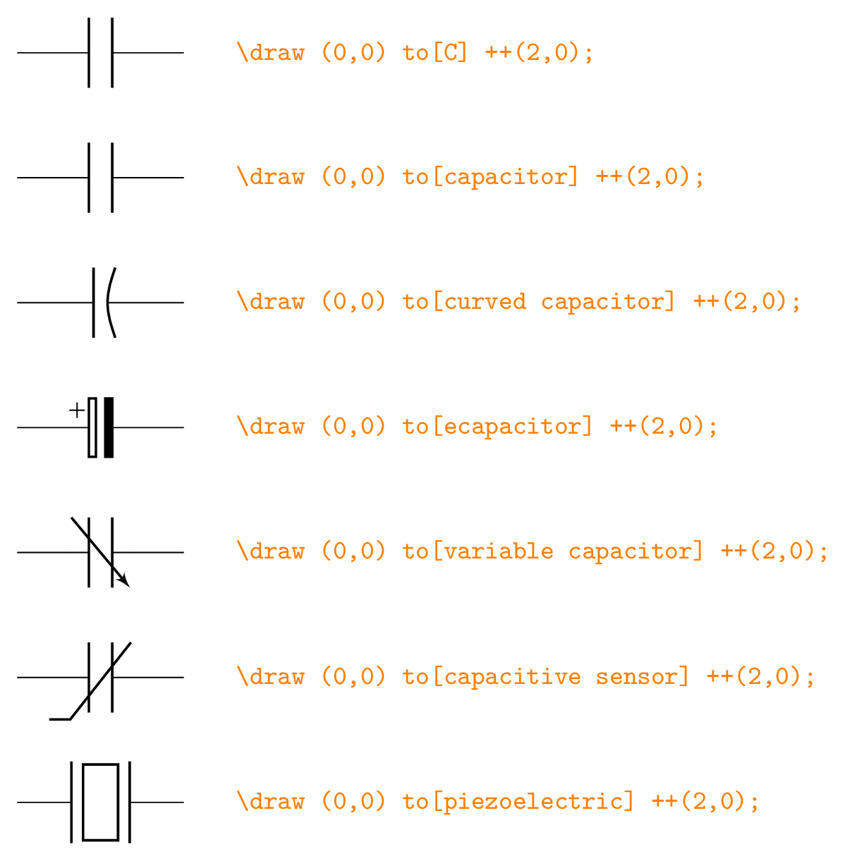
Different Capacitor styles
Step 6: Change components size
Components can be scaled using the command \ctikzset as follows:
\ctikzset{
resistors/scale=0.7,
capacitors/scale=0.7,
diodes/scale=0.7,
inductors/coils=6
}
Without components scaling

DC-DC buck converter drawn in LaTeX using CircuiTikZ
At this level, we have reached the end of this tutorial. Share with us your thoughts, reach us at admin@latexdraw.com, we will be happy to hear from you!


Very nice. A suggestion: if you want to avoid starting with positioning the node element, you can use the
anchor option: like (I do not know if HTML tags will work in comments):\draw (0,0) to[battery1,invert,l=$v_{in}$] ++(0,3) --
++(1,0) node[nigfete,rotate=90,label=S, anchor=D] (switch){};
so you can avoid the awkward absolute position of the switch.That’s really amazing and useful, Many thanks Romano!