Special thanks!
This tutorial has been revealed in buy me a coffee timeline and supported by Rafal  . I am very thankful to him and to all you guys for your encouraging feedback, comments and suggestions.
This keeps me motivated to create more TikZ tutorials.
All the best!

How to draw a neuron in TikZ
A neuron is represented by a circle which may be filled with a color as the above illustration. Drawing a circle in TikZ can be achieved using a node command with draw and circle options. Please check the tutorial TikZ shapes: circle for more details.
Here is an example of drawing two neurons filled with orange color. Adding a draw=<color> option to the node command will draw the circle border with the specified color:
\documentclass[border = 0.2cm]{standalone}

% Required package
\usepackage{tikz}

\begin {document}

\begin{tikzpicture}
	\node[circle, minimum size = 6mm,fill=orange!30] (Input-1) at (0,-1) {};
	\node[circle, minimum size = 6mm,fill=orange!30] (Input-1) at (0,-2) {};
\end{tikzpicture}

\end {document}

Both circles have the same minimum size which is equal to 6mm. As these neurons correspond to the input layer, we named the coordinates of the first circle as (Input-1) and the second circle as (Input-2). We will use these coordinates to connect different neurons of different layers.
Use a Loop to draw a set of neurons
To avoid repeating several line codes with the same structure, we can create a loop for that. In LaTeX, this corresponds to foreach command, check this post: How to use foreach loop in LaTeX.
Consider the above example of the three layers: 2 neurons for the Input layer, 5 neurons for the hidden layer and 2 neurons for the output layer:
\documentclass[border = 0.2cm]{standalone}

% Required package
\usepackage{tikz}

\begin {document}

\begin{tikzpicture}

% Input Layer
\foreach \i in {1,2}
{
	\node[circle,
		minimum size = 6mm,
		fill=orange!30] (Input-\i) at (0,-\i) {};
}

% Hidden Layer
\foreach \i in {1,2,...,5}
{
	\node[circle,
		minimum size = 6mm,
		fill=teal!50] (Hidden-\i) at (2.5,-\i) {};
}

% Output Layer
\foreach \i in {1,2}
{
	\node[circle,
		minimum size = 6mm,
		fill=purple!50] (Output-\i) at (5,-\i) {};
}

\end{tikzpicture}

\end {document}
Compiling this code yields the following illustration:

Comments:
- The input layer has two neurons which means that the loop variable \i takes values from the set {1,2}. This is the same as the output layer. The hidden layer has 5 neurons which means that \i takes values from the set {1,2,3,4,5}.
- The loop variable is used to save the coordinates of each neuron in each layer. For example: neuron 1 of the input layer has the coordinate (Input-1), neuron 3 of the hidden layer has the coordinate (Hidden-3) and neuron 2 of the output layer has the coordinates (Output-2).
Shifting along the y-axis in TikZ
From the previous illustration, we should shift all neurons of the hidden layer along the y-axis by:

where y1 (y2) is the length of the set of neurons of the input (hidden) layer, respectively. This also applies for the output layer. In this example, we have y1=1cm, y2=4cm.
As the distance between successive neurons is the same for the three layers, the above formula can be simplified as follows:

where n1 (n2) is the number of neurons of the input (hidden) layer, respectively.

Before implementing the above formula in the previous LaTeX code, Let's consider a general case with any number of neurons in each layer.
Define the number of neurons as a variable
In order to make the illustration customizable, we can create variables for the number of neurons in each layer. This can be achieved in LaTeX using \newcommand as follows:
% Input layer neurons'number
\newcommand{\inputnum}{3}

% Hidden layer neurons'number
\newcommand{\hiddennum}{5}

% Output layer neurons'number
\newcommand{\outputnum}{2}
These variables can be used in different foreach loops and shifting of hidden and output layers. Here is the corresponding code of 3 input neurons, 5 hidden layer neurons and 3 output neurons:
\documentclass[border = 0.2cm]{standalone}

% Required package
\usepackage{tikz}

\begin {document}

% Input layer neurons'number
\newcommand{\inputnum}{3}

% Hidden layer neurons'number
\newcommand{\hiddennum}{5}

% Output layer neurons'number
\newcommand{\outputnum}{2}

\begin{tikzpicture}

% Input Layer
\foreach \i in {1,...,\inputnum}
{
	\node[circle,
		minimum size = 6mm,
		fill=orange!30] (Input-\i) at (0,-\i) {};
}

% Hidden Layer
\foreach \i in {1,...,\hiddennum}
{
	\node[circle,
		minimum size = 6mm,
		fill=teal!50,
		yshift=(\hiddennum-\inputnum)*5 mm
	] (Hidden-\i) at (2.5,-\i) {};
}

% Output Layer
\foreach \i in {1,...,\outputnum}
{
	\node[circle,
		minimum size = 6mm,
		fill=purple!50,
		yshift=(\outputnum-\inputnum)*5 mm
	] (Output-\i) at (5,-\i) {};
}

\end{tikzpicture}

\end {document}
Compiling the above code yields:

Example of 3-5-2 Neural network
Nested loop in LaTeX
Each neuron of the input layer has to be connected with all neurons of the hidden layer. In addition, each neuron of the later has to be connected with all neurons of the output layer. To achieve this, we need to create a nested loop (a loop within a loop). Check the following code:
\documentclass[border = 0.2cm]{standalone}

% Required package
\usepackage{tikz}

\begin {document}

% Input layer neurons'number
\newcommand{\inputnum}{3}

% Hidden layer neurons'number
\newcommand{\hiddennum}{5}

% Output layer neurons'number
\newcommand{\outputnum}{2}

\begin{tikzpicture}

% Input Layer
\foreach \i in {1,...,\inputnum}
{
	\node[circle,
		minimum size = 6mm,
		fill=orange!30] (Input-\i) at (0,-\i) {};
}

% Hidden Layer
\foreach \i in {1,...,\hiddennum}
{
	\node[circle,
		minimum size = 6mm,
		fill=teal!50,
		yshift=(\hiddennum-\inputnum)*5 mm
	] (Hidden-\i) at (2.5,-\i) {};
}

% Output Layer
\foreach \i in {1,...,\outputnum}
{
	\node[circle,
		minimum size = 6mm,
		fill=purple!50,
		yshift=(\outputnum-\inputnum)*5 mm
	] (Output-\i) at (5,-\i) {};
}

% Connect neurons In-Hidden
\foreach \i in {1,...,\inputnum}
{
	\foreach \j in {1,...,\hiddennum}
	{
		\draw[->, shorten >=1pt] (Input-\i) -- (Hidden-\j);
	}
}

% Connect neurons Hidden-Out
\foreach \i in {1,...,\hiddennum}
{
	\foreach \j in {1,...,\outputnum}
	{
		\draw[->, shorten >=1pt] (Hidden-\i) -- (Output-\j);
	}
}

% Inputs
\foreach \i in {1,...,\inputnum}
{
	\draw[<-, shorten <=1pt] (Input-\i) -- ++(-1,0)
		node[left]{$x_{\i}$};
}

% Outputs
\foreach \i in {1,...,\outputnum}
{
	\draw[->, shorten <=1pt] (Output-\i) -- ++(1,0)
		node[right]{$y_{\i}$};
}

\end{tikzpicture}

\end{document}
- We added -> to the draw command in order to indicate that the straight line ends with an arrowhead. For more styles, check the post TikZ arrows.
- We added shorten >=1pt to create a small space of 1pt between the arrowhead and the neuron's border.
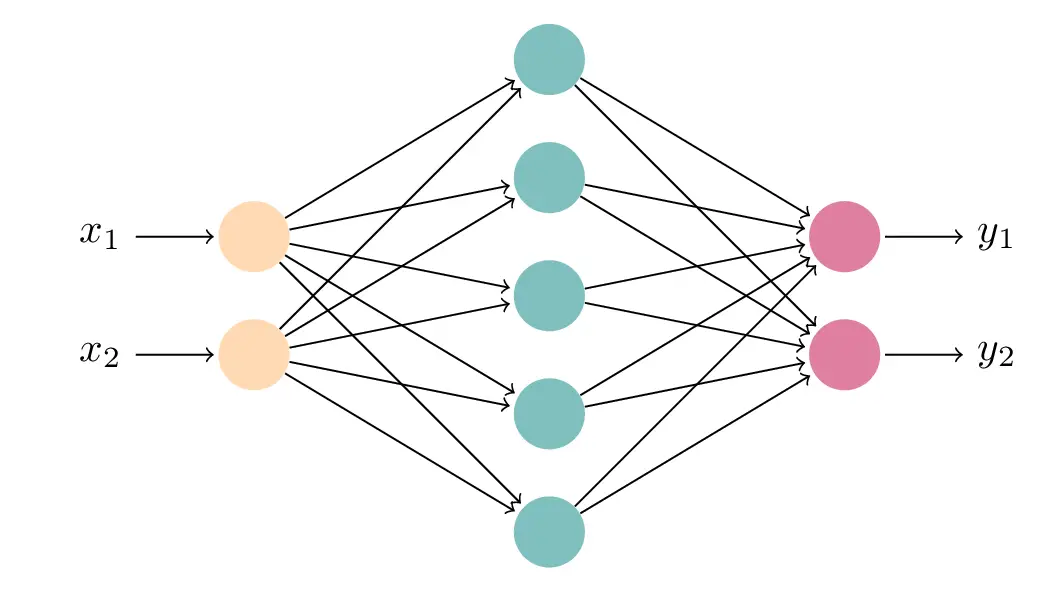
Adding this piece of code to the previous one and for the parameters 2-5-2 of the Neural network, we get the following result:

Example of 2-5-2 Neural network
We reached the end of Today's tutorial. If you enjoy these TikZ tutorials, Please consider supporting LaTeXdraw.com by buying me a coffee in: