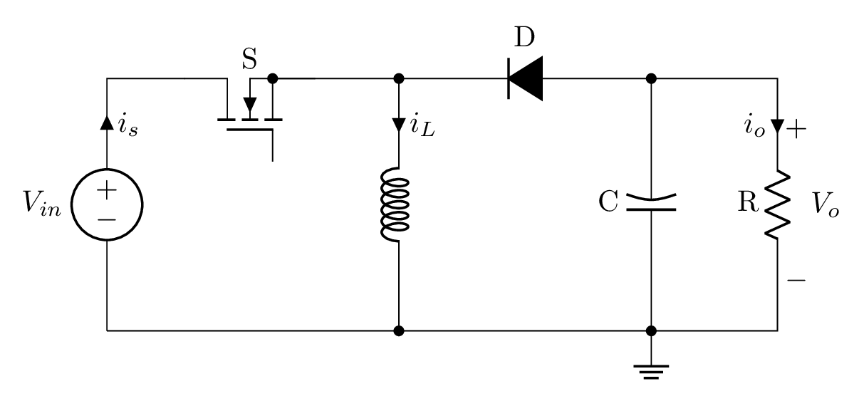
Short description
The topology of the Buck-Boost converter is shown above which has the following electrical components:
- a DC input voltage
- a load resistor R,
- a filter capacitor C,
- an inductor L
- and two complementary switches.
Drawing these elements in LaTeX can be achieved using CircuiTikZ package, built using TikZ/PGF.
Buck Boost converter CircuiTikZ code
The TikZ code of the buck-boost converter is given below:
\documentclass[border=0.2cm]{standalone}

% Load the package
\usepackage{circuitikz}

\begin{document}

\begin{tikzpicture}[american]

% Change components size
\ctikzset{
	resistors/scale=0.7,
	capacitors/scale=0.7,
	diodes/scale=0.7,
	inductors/coils=6
}

% Draw Voltage and switch
\draw (0,0) to[V,
	invert,
	l=$V_{in}$,
	i_>=$i_s$] ++(0,3) -- ++(1,0)
node[nigfete,
	rotate=90,
	label=S,
	solderdot,
	anchor=D](switch){};

\draw (switch.E) -- ++(1,0)
	coordinate(a1);

% Draw Diode
\draw (a1) to[D*,l= D,invert] ++(3,0)
	coordinate(a2);

% Draw resistor
\draw (a2) -- ++(1.5,0)
	to[R,
		l_=R,
		v^>=$\:V_o$,
		i>_=$i_o$] ++(0,-3) -- ++(-1.5,0) coordinate(a3);

% Draw ground
\node[ground] at (a3) {};

% Bottom lines
\draw (a3) -- ++(-3,0)
	coordinate(a4);
\draw (a4) -- (0,0);

% Draw capacitor
\draw (a3) to[curved capacitor,*-*,l=C] (a2);

% Draw inductor
\draw (a4) to[cute inductor,*-*,i_<=$i_L$] (a1); %

\end{tikzpicture}

\end{document}
