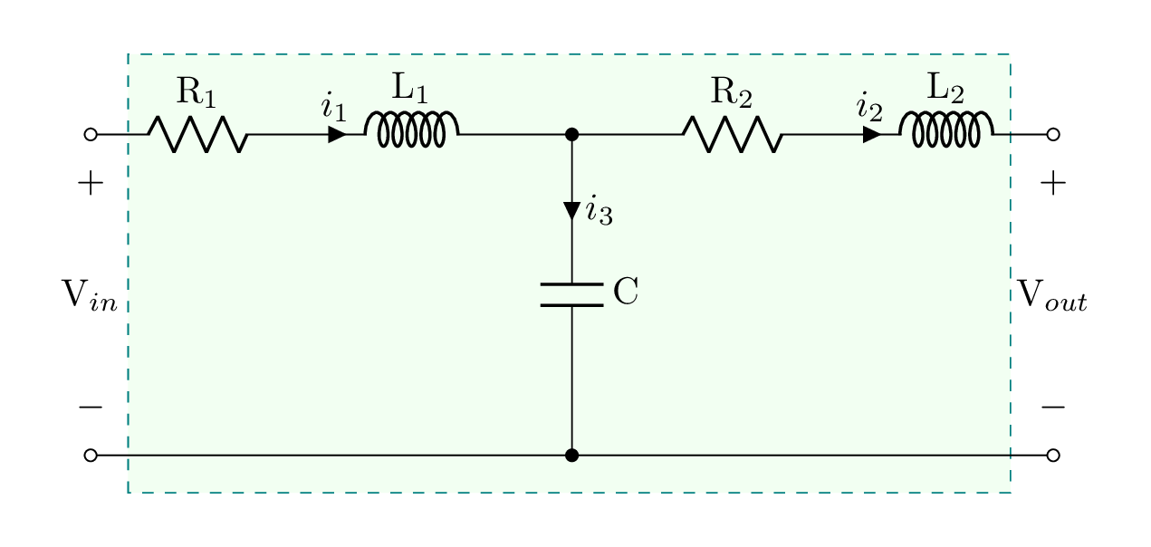
- This tutorial is dedicated to drawing an LCL filter in LaTeX using CircuiTikZ package. We will learn how to draw resistors, inductors and capacitors. Moreover, we will highlight how to add currents arrows to the circuit and voltage labels to open circuits.
Short description
- The LCL filter consists of non-ideal inductors (+ resistor) and a capacitor. All elements have labels and input currents. Moreover, we have input and output voltage labels. Check the code below!
LaTeX code of the LCL filter
\documentclass[border=0.5cm]{standalone}

% Package
\usepackage[RPvoltages]{circuitikz}

\begin{document}

\begin{tikzpicture}[american]

% Components size
\ctikzset{
	resistors/scale=0.8,
	capacitors/scale=0.7,
	inductors/coils=6
}

% Background green
\draw
[
	teal,
	dashed,
	fill=green!5
] (0.35,-0.35) rectangle (8.6,3.75);

% Circuit code
\draw (0,3) to[R,l=R$_1$,o-] ++(2,0)
	to[cute inductor,l=L$_1$,i>^=$i_1$] ++(2,0)
	to[short] ++(0.5,0) coordinate(a)
	to[short] ++(0.5,0)
	to[R,l=R$_2$] ++ (2,0)
	to[cute inductor,l=L$_2$,i>^=$i_2$,-o] ++(2,0);

\draw (0,0) to[short,o-] ++(4.5,0)coordinate(b)
	to[short,-o] ++(4.5,0);

% Capacitor
\draw (a) to[C,l=C,*-*,i>^=$i_3$] (b);

% Voltage labels
\draw (0,3) to[open,v=V$_{in}$] ++(0,-3);
\draw (9,3) to[open,v=V$_{out}$] ++(0,-3);

\end{tikzpicture}

\end{document}- If you would to write a detailed tutorial about it, leave me a comment below or reach me via e-mail at admin@latexdraw.com, I will be happy to hear from you!

