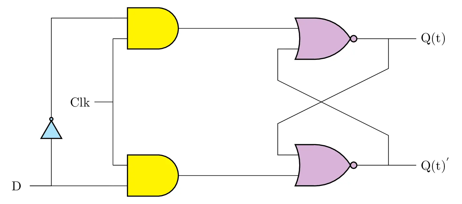
- In this post, we will learn how to draw a D Flip Flop circuit, known also as D Latch, in LaTeX using CircuiTikZ package. We will learn how to access inputs and outputs of logic gates, align outputs with inputs of two connected logic gates.
Short description
- The D latch circuit consists of the following gates: and port, nor port and not port. These ports corresponds IEEESTD styles which are provide by the circuitikz package. We need to align the output of the top and logic gate with the first input of the nor logic gate which can be achieved by specifying anchors of each logic gate. Check the below code !
LaTeX code of the D Latch
\documentclass[border=0.2cm]{standalone}

% Package
\usepackage[american]{circuitikz}

\begin{document}

\begin{tikzpicture}

% Draw and gates
\node[ieeestd and port, fill=yellow] (and1) at (0,2) {};
\node[ieeestd and port, fill=yellow] (and2) at (0,-2) {};

% Draw nor gates
\draw (and1.out) -- ++(2.5,0) node
[
	ieeestd nor port,
	fill=violet!30,
	anchor=in 1
] (nor1) {};

\draw (and2.out) -- ++(2.5,0) node
[
	ieeestd nor port,
	fill=violet!30,
	anchor=in 2
] (nor2) {};

\draw (nor1.in 2) -| ++ (-0.2,-0.85) -- ++(3,-1.5) coordinate(a) |- (nor2.out);
\draw (nor2.in 1) -| ++ (-0.2,0.85) -- ++(3,1.5) |- (nor1.out);

% Clock
\draw (and1.in 2) -- (and2.in 1)node[midway](clk){};
\draw (clk.center) -- ++(-0.5,0) node[left]{Clk};

% Output labels
\draw (nor1.out -| a) -- ++(0.75,0) node[right]{Q(t)};
\draw (nor2.out -| a) -- ++(0.75,0) node[right]{Q(t)$^{'}$};

\draw (and2.in 2) -- ++(-2.25,0) coordinate(a2) node[left=0.1cm]{D};

% Not port
\node
[
	ieeestd not port,
	rotate=90,
	scale=0.5,
	fill=cyan!30
](not) at (-2.75,-0.75){};

\draw (not.in) |- (a2) (not.out) |- (and1.in 1)  ;

\end{tikzpicture}

\end{document}- If you would to write a detailed tutorial about it, leave me a comment below or reach me via e-mail at admin@latexdraw.com, I will be happy to hear from you!


