1. Let's start by the ground
We will start by drawing the floor. We draw the components in a brown tone (brown!80!red) and add the dots using patterns TikZ library, which includes crosshatch dots option. Hence, the ground can be drawn in two steps:
1) we draw a rectangle (without borders) and we fill it with a pattern (crosshatch dots). To this end, we need to load patterns TikZ library.
2) Then, we draw the above side of the rectangle (a straight line).

Here is the corresponding LaTeX code:
\documentclass[border = 0.2cm]{standalone}

% Required packages and libraries
\usepackage {tikz}
\usetikzlibrary {patterns}

\begin{document}

\begin{tikzpicture} [thick]

% ground
\draw [brown!80!red] (-2,0) -- (2,0);
\fill [pattern = crosshatch dots,
	pattern color = brown!80!red] (-2,0) rectangle (2,-.2);

\end{tikzpicture}

\end{document}
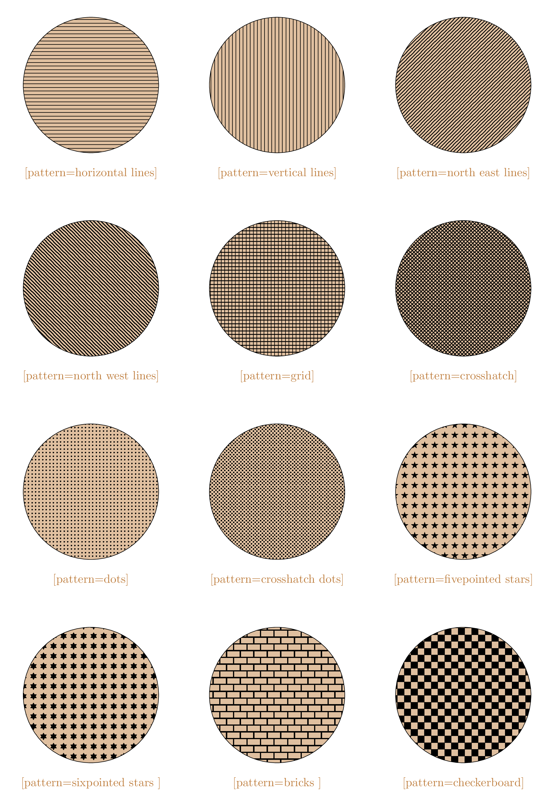
Check the following list of patterns for more styles:

2. Cart and Pendulum
We will use an angle variable \ang throughout the diagram which will stand for the angle of inverted pendulum. In our example, it will be 30degrees. Also, most of our line will be thick and most of the text will be in a smaller font (\footnotesize), so we declare these as styling options to our tikzpicture environment:
% ...
\begin{tikzpicture} [font = \footnotesize, thick]

% Angle of Pendulum
\newcommand{\ang}{30}

% ground
% ...
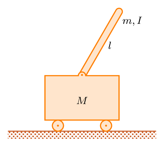
Then we will start the cart and the inverted pendulum on top of it. These elements will use the same styling for their colors—to declare these without effecting other elements, we draw these elements in a scope environment and add our coloring options. We also declare a new style to put small orange dots (radius = .025) for the wheels and pivot point.
Here is the corresponding LaTeX code of Cart, Pendulum and ground:
\documentclass[border = 0.2cm]{standalone}

% Required packages and libraries
\usepackage {tikz}
\usetikzlibrary {patterns}

\begin{document}

\begin{tikzpicture} [thick]

% Angle of Pendulum
\newcommand{\ang}{30}

% ground
\draw [brown!80!red] (-2,0) -- (2,0);
\fill [pattern = crosshatch dots,
	pattern color = brown!80!red] (-2,0) rectangle (2,-.2);

% cart
\begin{scope} [draw = orange,
	fill = orange!20,
	dot/.style = {orange, radius = .025}]

\filldraw [rotate around = {-\ang:(0,1.5)}] (.09,1.5) --
	node [midway, right] {$l$}
	node [very near end, right] {$m,I$}
	+(0,2) arc (0:180:.09)
	coordinate [pos = .5] (T) -- (-.09,1.5);

\filldraw (-.65,.15) circle (.15);
\fill [dot] (-.65,.15) circle;
\filldraw (.65,.15) circle (.15);
\fill [dot] (.65,.15) circle;

\filldraw (-1,1.5) -- coordinate [pos = .5] (F)
	(-1,.3) -- node [above = .3cm] {$M$}
	(1,.3) -- (1,1.5)
	coordinate (X) -- (.1,1.5)
	arc (0:180:.1) -- (-1.014,1.5);

\fill [dot] (0,1.52) circle;
\end{scope}

\end{tikzpicture}

\end{document}
Code comments:
- We draw the wheels as circles with .15 cm radius and place them on top of the floor line. Then we add the dots to make them look more like wheels.
- Then we draw the cart—we will draw it with a height of 1.2 cm and length of 2 cm. We start drawing the line from the top left point, while drawing down we place coordinate (F) to use later to draw a force. We draw from 1.5 to 0.3 in y axis to stop right before the wheels. Then we draw the bottom line of the cart and use it to place a label inside our cart by adding a node.
- Then we will draw up for the right line of the cart and add another coordinate (X) to use later. While drawing the top line, we need to add a pivot point to the cart.
- To place the pivot point, we will draw the line towards the middle point until 1 mm remains. Then we use an arc with arc (0:180:.1) command, which tells TikZ to draw an arc with an angle of 180degrees counterclockwise and with a radius of 1 mm.
- After the arc, we will finish our line by drawing until our starting point. Here, we added a small value to our end coordinate to compensate for the line thickness. (A thick line in TikZ is 0.8 pt, which is about 0.028 cm. That's why we added half of a line width, 0.014 cm to the x component of our end coordinate to fill the emptiness on the left corner.)
- For the final touch, we will add a dot for our pendulum pivot at the top middle point of our cart and 2 mm towards the arc.
- Then we will add the inverted pendulum. We draw its lines 0.1 mm inside of the arc. While drawing upwards, we will place our labels to the middle (l) and near end (m,I) of the line. After drawing upwards 2 cm, we will add another arc for the top point of the pendulum. We will add another coordinate (T) to use later. Then we will draw down to meet the pivot point.
- To give our pendulum an angle, we will add rotate around option with {-\ang:(0,1.5)} parameter, which will make it rotate 30degrees around the pivot point. We will place this line of command to the top of the cart scope to avoid overlapping with the cart lines.
- Pendulum angle label
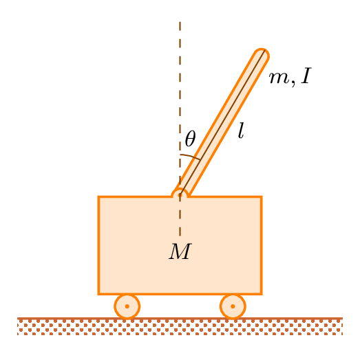
In this section, we will draw the guiding lines and the angle for the pendulum. These lines will be thin and have a darker tone (orange!50!black), so we give these styling option to a new scope for these elements.
We will start drawing from the top of the pendulum using (T) coordinate to the pivot point, to which we add a shortcut here (P). Then we will draw from 5 mm downwards the pivot point to 2.2 cm upwards with dashed lines.
- To show the angle, we use an arc which will start 5 mm above of the P coordinate. We need to draw from 90 to 90-\ang, which we declare by the command (90:90-\ang:.5). We placed a theta symbol in a node above the arc to represent the angle.

\documentclass[border = 0.2cm]{standalone}

% Required packages and libraries
\usepackage {tikz}
\usetikzlibrary {patterns}

\begin{document}

\begin{tikzpicture} [thick]

% Angle of Pendulum
\newcommand{\ang}{30}

% ground
\draw [brown!80!red] (-2,0) -- (2,0);
\fill [pattern = crosshatch dots,
	pattern color = brown!80!red] (-2,0) rectangle (2,-.2);

% cart
\begin{scope} [draw = orange,
	fill = orange!20,
	dot/.style = {orange, radius = .025}]

\filldraw [rotate around = {-\ang:(0,1.5)}] (.09,1.5) --
	node [midway, right] {$l$}
	node [very near end, right] {$m,I$}
	+(0,2) arc (0:180:.09)
	coordinate [pos = .5] (T) -- (-.09,1.5);

\filldraw (-.65,.15) circle (.15);
\fill [dot] (-.65,.15) circle;
\filldraw (.65,.15) circle (.15);
\fill [dot] (.65,.15) circle;

\filldraw (-1,1.5) -- coordinate [pos = .5] (F)
	(-1,.3) -- node [above = .3cm] {$M$}
	(1,.3) -- (1,1.5)
	coordinate (X) -- (.1,1.5)
	arc (0:180:.1) -- (-1.014,1.5);

\fill [dot] (0,1.52) circle;
\end{scope}

% lines and angles
\begin{scope} [thin, orange!50!black]
	\draw (T) -- (0,1.52) coordinate (P);
	\draw [dashed] (P) + (0,-.5) -- +(0,2.2);
	\draw (P) + (0,.5) arc (90:90-\ang:.5) node [black, midway, above] {$\theta$};
\end{scope}

\end{tikzpicture}

\end{document}
- Draw free body diagram
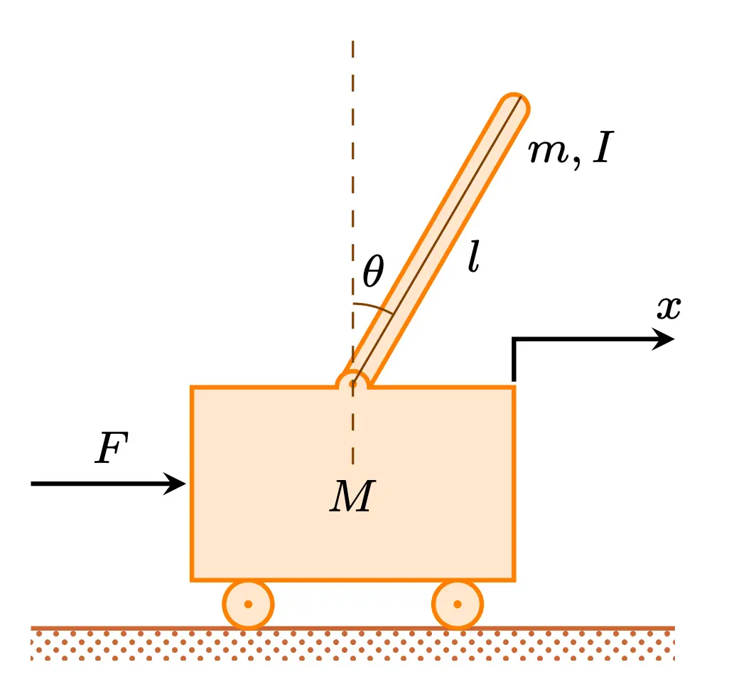
Finally, we will draw our force and direction. We will use stealth arrow tips.
- We will draw the first line from F coordinate to 1 cm left. We will draw it with a backwards arrow option (stealth-) to put the arrow tip the the starting point of our line.
- Then we will draw the direction by starting from X coordinate towards 1 cm right and 3 mm above. We will use |- option to draw with two perpendicular lines. As a final touch we add our labels using nodes and finish our diagram.
Final code of inverted pendulum with cart:
\documentclass[border = 0.2cm]{standalone}

% Required packages and libraries
\usepackage {tikz}
\usetikzlibrary {patterns}

\begin{document}

\begin{tikzpicture} [thick]

% Angle of Pendulum
\newcommand{\ang}{30}

% ground
\draw [brown!80!red] (-2,0) -- (2,0);
\fill [pattern = crosshatch dots,
	pattern color = brown!80!red] (-2,0) rectangle (2,-.2);

% cart
\begin{scope} [draw = orange,
	fill = orange!20,
	dot/.style = {orange, radius = .025}]

\filldraw [rotate around = {-\ang:(0,1.5)}] (.09,1.5) --
	node [midway, right] {$l$}
	node [very near end, right] {$m,I$}
	+(0,2) arc (0:180:.09)
	coordinate [pos = .5] (T) -- (-.09,1.5);

\filldraw (-.65,.15) circle (.15);
\fill [dot] (-.65,.15) circle;
\filldraw (.65,.15) circle (.15);
\fill [dot] (.65,.15) circle;

\filldraw (-1,1.5) -- coordinate [pos = .5] (F)
	(-1,.3) -- node [above = .3cm] {$M$}
	(1,.3) -- (1,1.5)
	coordinate (X) -- (.1,1.5)
	arc (0:180:.1) -- (-1.014,1.5);

\fill [dot] (0,1.52) circle;
\end{scope}

% lines and angles
\begin{scope} [thin, orange!50!black]
	\draw (T) -- (0,1.52) coordinate (P);
	\draw [dashed] (P) + (0,-.5) -- +(0,2.2);
	\draw (P) + (0,.5) arc (90:90-\ang:.5) node [black, midway, above] {$\theta$};
\end{scope}

% forces
	\draw [stealth-] (F) -- node [above] {$F$} + (-1,0);
	\draw [-stealth] (X) |- node [very near end, above right] {$x$} + (1,.3);

\end{tikzpicture}

\end{document}
