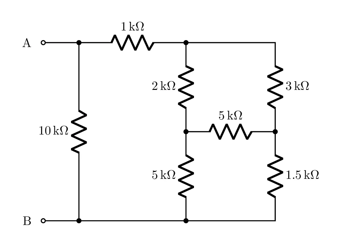
- This tutorial is about drawing a simple circuit diagram which consists of series and parallel resistors in LaTeX using CircuiTikZ package. We will learn how to add units to resistors' labels using the package siunitx.
Short description
- The circuit consists of series and parallel resistors. For labels, we use siunitx package to be able to add units directly (ohms in ours case). We need to save coordinates along the path in order to use them to draw intermediate resistors. Check the below code!
LaTeX code of the series and parallel resistors circuit
\documentclass[border=0.5cm]{standalone}

% Packages
\usepackage{siunitx}
\usepackage[RPvoltages]{circuitikz}

\begin{document}

\begin{tikzpicture}[american,thick]

% Circuit code
\draw (0,0)node[left=0.2cm]{B}
	to[short,o-] ++(1,0) coordinate(b1)
	to[short] ++(3,0) coordinate (b2)
	to[short] ++ (2.5,0)
	to[R,l_=$\SI{1.5}{\kilo\ohm}$] ++(0,2.5)  coordinate (c1)
	to[R,l_=$\SI{3}{\kilo\ohm}$] ++(0,2.5)
	to[short] ++(-2.5,0) coordinate (a2)
	to[R,l_=$\SI{1}{\kilo\ohm}$]++(-3,0) coordinate (a1)
	to[short,-o] ++(-1,0) node[left=0.2cm]{A} ;

\draw (a1) to[R,l_=$\SI{10}{\kilo\ohm}$,*-*] (b1);

\draw (c1) to[R,l_=$\SI{5}{\kilo\ohm}$,*-] ++ (-2.5,0)coordinate (c2);

\draw (c2) to[R,l=$\SI{2}{\kilo\ohm}$,-*] (a2);
\draw (c2) to[R,l_=$\SI{5}{\kilo\ohm}$,*-*] (b2);


\end{tikzpicture}

\end{document}- If you would to write a detailed tutorial about it, leave me a comment below or reach me via e-mail at admin@latexdraw.com, I will be happy to hear from you!

