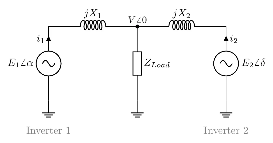

Short description
LaTeX code of the equivalent model of two inverters
 \documentclass[border=0.2cm]{standalone}

% Package
\usepackage[RPvoltages]{circuitikz}

\begin{document}

\begin{circuitikz}[american]

% Components size
\ctikzset{
	resistors/scale=0.7,
	capacitors/scale=0.7,
	diodes/scale=0.7,
	inductors/coils=6
}

% Circuit Code
\draw (0,0) node[ground]{}
	to[sV,l=$E_1 \angle{ \alpha}$,i=$i_1$] ++(0,2.5)
	to[cute inductor,l=$jX_1$,-*] ++(3,0)
	node[above]{\small $V \angle{0}$} coordinate(MidPoint)
	to[cute inductor,l=$jX_2$] ++(3,0)
	to[sV,l=$E_2 \angle{ \delta}$,i<=$i_2$] ++(0,-2.5)node[ground]{};

\draw (MidPoint) to[european resistor, l=$Z_\mathrm{load}$] ++(0,-2.5)
	node[ground]{};

% Labels
\node[gray] at (0,-1){Inverter 1};
\node[gray] at (6,-1){Inverter 2};

\end{circuitikz}

\end{document}
Special thanks to Hans Schülein for his remark about labelling the circuit, I really appreciate it!