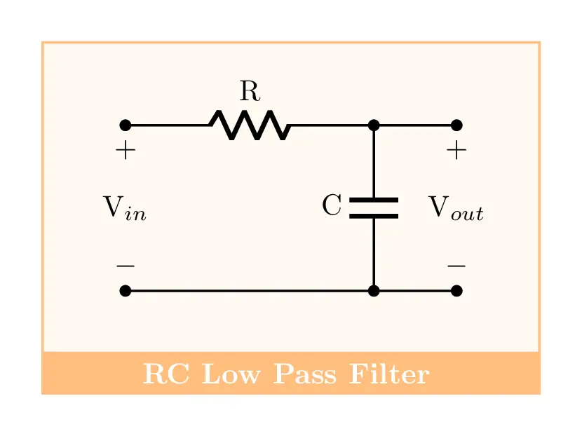
- This post is about drawing a low-pass filter (LPF), type RC, in LaTeX using TikZ and CircuiTikZ packages. Unlike the high pass filter, LPF passes signals with a frequency lower than a certain cutoff frequency and attenuates signals with frequencies higher than the cutoff frequency.
Short description
- The RC low pass filter circuit diagram has two electrical components: a resistor and a capacitor. Both components have labels (R for the resistor and C for the capacitor). In addition, it has voltage labels which can be created by using the open circuit element. Moreover, the circuit is drawn above a rectangle filled with orange color. Check the code below!
LaTeX code of RC Low pass filter circuit
\documentclass[border=0.5cm]{standalone}

% Packages
\usepackage[RPvoltages]{circuitikz}


\begin{document}

\begin{tikzpicture}[american,thick]

% Change components size
\ctikzset{
	resistors/scale=0.8,
	capacitors/scale=0.7,
}

% Orange boxes
\draw
[
	fill=orange!5,
	draw=orange!50
] (-1,-0.75) rectangle(5,3);

\node
[
	align=center,
	minimum width=6cm,
	fill=orange!50,
	text=white,
	draw=orange!50
] at (2,-1){\textbf{RC Low Pass Filter} };

% Circuit code
\draw (0,0) to[short,*-*] ++ (4,0);
\draw (0,2) to[R=R,*-] ++ (3,0) coordinate(a);
\draw (a) to[short,-*] ++ (1,0);
\draw (a) to[C,l_=C,*-*] ++(0,-2);

% Voltage labels
\draw (0,2) to[open,v=V$_{in}$] ++(0,-2);
\draw (4,2) to[open,v=V$_{out}$] ++(0,-2);

\end{tikzpicture}

\end{document}
- If you would to write a detailed tutorial about it, leave me a comment below or reach me via e-mail at admin@latexdraw.com, I will be happy to hear from you!

