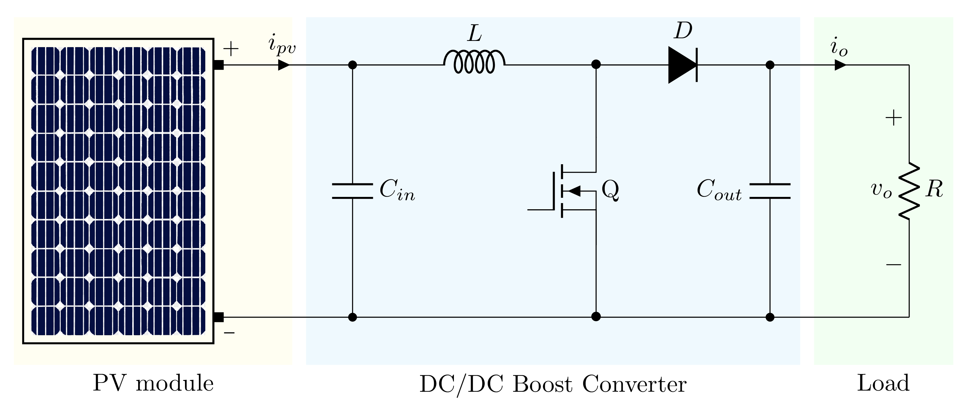
Short description
LaTeX code of the boost converter
 \documentclass[border=0.2cm]{standalone}

% Packages
\usepackage{circuitikz}
\usetikzlibrary{calc} % coordinate calculation


\begin{document}

\begin{circuitikz}[american]

% Scale components
\ctikzset{
	resistors/scale=0.7,
	capacitors/scale=0.7,
	diodes/scale=0.7,
}

% PV module label
\fill[fill=yellow!5] (-1.5,-2.5) rectangle (2.5,2.5)
node[midway,below=2.5cm,black]{{PV module}};

% Boost converter label
\fill [cyan!5] (2.7,-2.5) rectangle (9.8,2.5)
	node[midway,below=2.5cm,black]{{DC/DC Boost Converter}};

% Load label
\fill [green!5] (10,-2.5) rectangle (12,2.5)
	node[midway,below=2.5cm,black]{Load};

% Add an image in TikZ
\node[
	draw,
	thick,
	outer sep=0pt
] (panel) at (0,0) {\includegraphics[width=2.5cm]{PV-module}};

% Top horizontal path (L,D)
\draw (panel.53) to [short,i=$i_{pv}$] ++(2,0) coordinate(a1)
	to[cute inductor,l=$L$] ++(3.5,0) coordinate(b1)
	to[D*,l=$D$] ++(2.5,0) coordinate(c1)
	to [short,i=$i_{o}$] ++(2,0)coordinate(d1);

% Bottom horizontal path (L,D)
\draw (panel.-53) -- ++(2,0) coordinate(a2)
	-- ++(3.5,0) coordinate(b2)
	-- ++(2.5,0) coordinate(c2)
	-- ++(2,0)coordinate(d2);

% Add a resistor
\draw (d1) to[R, v_=$v_o$,l=$R$] (d2);

% Add input capacitor
\draw (a1) to[C,l=$C_{in}$,*-*] (a2);

% Add output capacitor
\draw (c1) to[C,l_=$C_{out}$,*-*] (c2);

% Add switch
\node[nigfete] (switch) at ($0.5*(b1)+0.5*(b2)$){ Q} ;
\draw (b1) node[]{$\bullet$}-- (switch.D);
\draw (b2) node[]{$\bullet$} -- (switch.E);

% Panel connectors
\node[fill=black,right,inner sep=2pt] at (panel.53){};
\node[above right] at (panel.53){\small +};

\node[fill=black,right,inner sep=2pt] at (panel.-53){};
\node[below right, inner ysep=6pt] at (panel.-53){\Large \_};

\end{circuitikz}

\end{document}
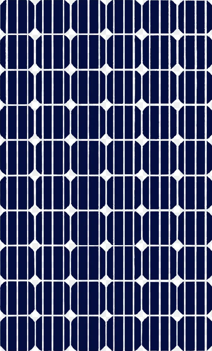
The code requires the following PV Panel image, download it and put it in the same folder with main LaTeX file:

