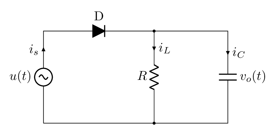
- PGF-TikZ is a powerful tool for creating sophisticated graphics with vector representation. It however lacks a good package for electric diagrams. Fortunately, CircuiTikZ was created for this purpose, it provides the necessary macros to layout circuit diagrams for academic use in no time and in a rather intuitive, flexible and easy manner. This tutorial is about drawing half wave rectifier in LaTeX using CircuiTikZ package.
Short description
- The half wave rectifier is an AC/DC power converter which is built based on a diode, capacitor and a resistive load. All these components are labeled and drawn along the drawing path. The input voltage is an AC source which corresponds to the option sV in CircuiTikZ. Check the code for more details!
LaTeX code of the half wave rectifier
 \documentclass[border=0.2cm]{standalone}

% Package
\usepackage[american]{circuitikz}

\begin{document}

\begin{tikzpicture}[voltage dir = RP]

\ctikzset{
	bipoles/length=0.8cm,
	bipoles/diode/height=0.4,
	bipoles/diode/width=0.4
}

% Circuit Code
\draw (0,0)
	to[sV,l=$u(t)$,i=$i_s$] (0,2.5) % The voltage source
	to[D*,l=D] (3,2.5) % The diode
	to[R,l_=$R$,i>^=$i_L$,*-*] (3,0) % The resistor
	to[short] (0,0);
\draw (3,2.5)
	to[short] (5,2.5)
	to[C,i>^=$i_C$,l=$v_o(t)$] (5,0) % The capacitor
	to[short] (3,0);
\end{tikzpicture}

\end{document}- If you would to see a detailed tutorial about it, leave me a comment below or reach me via e-mail at admin@latexdraw.com, I will be happy to hear from you!

