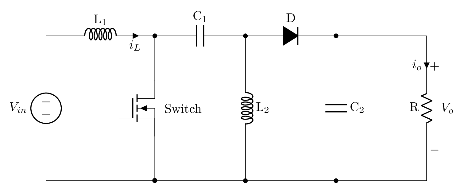
- This post is about drawing a dc-dc power converter, known as sepic converter, in LaTeX using CircuiTikZ package. SEPIC stands for single ended primary inductor converter. It allows the electrical voltage at its output to be greater than, less than, or equal to that at its input.
Short description
- The circuit consists of two types of electrical components: first one is drawn along the path which corresponds to voltage source, inductors, capacitors, resistors and diode. The second type is drawn as a node which corresponds to the switch. All elements are labeled using l=<labelName> option. Check the code below!
LaTeX code of the sepic circuit
 \documentclass[border=0.2cm]{standalone}

% Package
\usepackage[RPvoltages]{circuitikz}

\begin{document}

\begin{circuitikz}[american]

% Components size
\ctikzset{
	resistors/scale=0.7,
	capacitors/scale=0.7,
	diodes/scale=0.7,
	inductors/coils=6
}

% Draw switch
\node[nigfete] (switch)at (3,2){$\:$ Switch} ;

% Draw input voltageand inductor
\draw (0,0) to[american voltage source,l=$V_{in}$] ++(0,4)
	to[cute inductor,i_>=$i_L$,l=L$_1$,-*] ++(3,0) coordinate(a1);

% Draw capacitor and diode
\draw (a1) to[capacitor,l=C$_1$] ++(2.5,0) coordinate(a2)
	to[D*,l= D] ++(2.5,0) coordinate(a3) -- ++(2.5,0)coordinate(a4) ;

% Draw resistor
\draw (a4) to[R,l_=R,invert,v^=$\:V_o$,i>_=$i_o$] ++ (0,-4) -- (0,0);

% Draw second capacitor
\draw (a3) to[capacitor,l=C$_2$,*-*] ++(0,-4);

% Draw second inductor
\draw (a2) to[cute inductor,l=L$_2$,*-*] ++(0,-4);
\draw (a1) -- (switch.D) (switch.E)-- (3,0) node{$\bullet$};

\end{circuitikz}

\end{document}- If you would to see a detailed tutorial about it, leave me a comment below or reach me via e-mail at admin@latexdraw.com, I will be happy to hear from you!

