In this post, we will learn how to draw the free body diagram of Atwood's Machine in LaTeX using TikZ package. At the end of this tutorial, we will be able to:
- draw a circle, a rectangle and a trapezium;
- fill a shape with patterns and create smooth corners.
- draw arrows and add labels.
Start with the Pulley
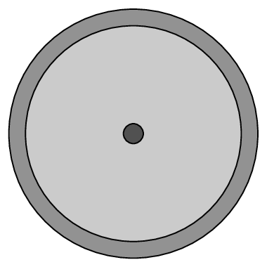
The pulley can be drawn by the mean of three circles with different sizes and colors. The origin of our illustration will be chosen as the center of these circles and from there we will draw different parts of the Atwood's machine.
The next LaTeX code shows how to draw these circles with the following specifications:
- Circle 1: has a radius of 1.5cm and filled with gray color.
- Circle 2: has a radius of 1.3cm and filled with light gray color.
- Circle 3: represents the axle of the pulley which has the smallest radius 0.12cm and filled with drak gray.
 \documentclass[border=0.1cm]{standalone}
\usepackage{tikz}

\begin{document}

\begin{tikzpicture}

% Pulley
\draw[fill = gray] (0,0) circle (1.5cm); % Big circle
\draw[fill=lightgray] (0,0) circle (1.3cm); % Medium circle
\draw[fill=darkgray] (0,0) circle (0.12cm); % Axle circle

\end{tikzpicture}

\end{document}
The pulley has an axle (small dark gray circle) attached to a supporting structure through a trapezium shape. The latter is drawn manually (not using predefined shapes) as follows:
 \documentclass[border=0.5cm]{standalone}
\usepackage{tikz}

\begin{document}

\begin{tikzpicture}

% Pulley
\draw[fill = gray] (0,0) circle (1.5cm); % Big circle
\draw[fill=lightgray] (0,0) circle (1.3cm); % Medium circle
\draw[fill=white] (75:2.5) -- (0.2,-0.25) -- (-0.2,-0.25) -- (105:2.5) -- cycle;
\draw[fill=darkgray] (0,0) circle (0.12cm); % Axle circle


\end{tikzpicture}

\end{document}
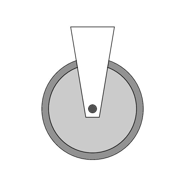
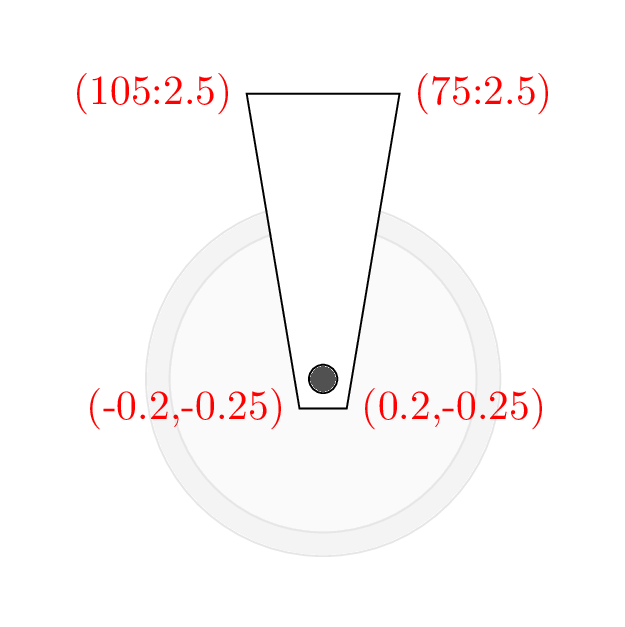
We have added a line code that simply draws a path between the four points.
You may remarked that the path (trapezium) has sharp corners and we would like to round it for the two bottom corners. This can be achieved using rounded corners but applying this to the \draw command will affect the 4 corners.
To avoid this issue, we will add this locally by using to[rounded corners=0.2cm] instead of --. Here is the corresponding LaTeX code:
 \documentclass[border=0.5cm]{standalone}
\usepackage{tikz}

\begin{document}

\begin{tikzpicture}

% Pulley
\draw[fill = gray] (0,0) circle (1.5cm); % Big circle
\draw[fill=lightgray] (0,0) circle (1.3cm); % Medium circle
\fill[white, opacity=0] (-1.6,-1.6) rectangle ++(3.2,3.2);
\draw[fill=white] (75:2.5) to[rounded corners=0.2cm] (0.2,-0.25) to[rounded corners=0.2cm] (-0.2,-0.25) -- (105:2.5) -- cycle;
\draw[fill=darkgray] (0,0) circle (0.12cm); % Axle circle


\end{tikzpicture}

\end{document}
Here is the obtained results and now we will draw the supporting structure.
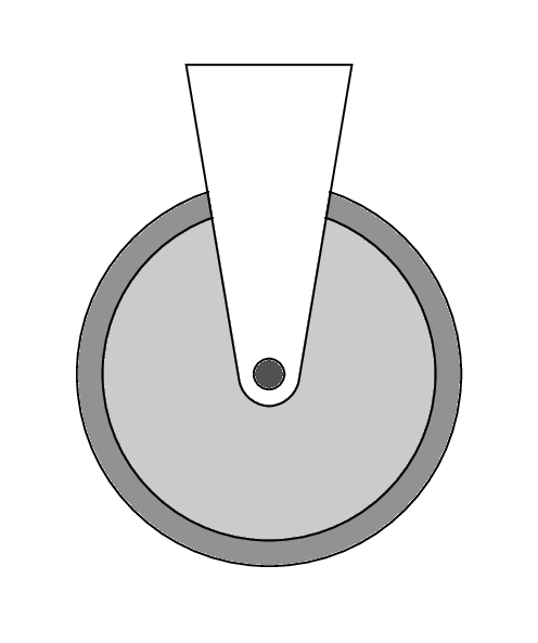
Filling shapes with Patterns in TikZ
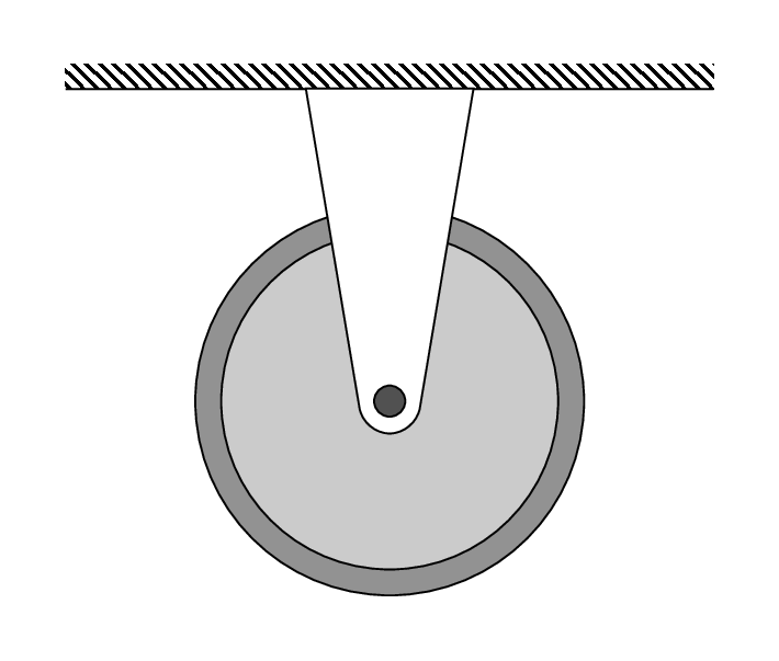
The supporting structure can be drawn in two steps:
1) we draw a rectangle (without borders) and we fill it with a pattern (diagonal lines),
2) we draw the bottom line of the rectangle.
TikZ Library patterns
Fortunately, there is a TikZ library named patterns which provides us a list of predefined patterns (see the illustration below).
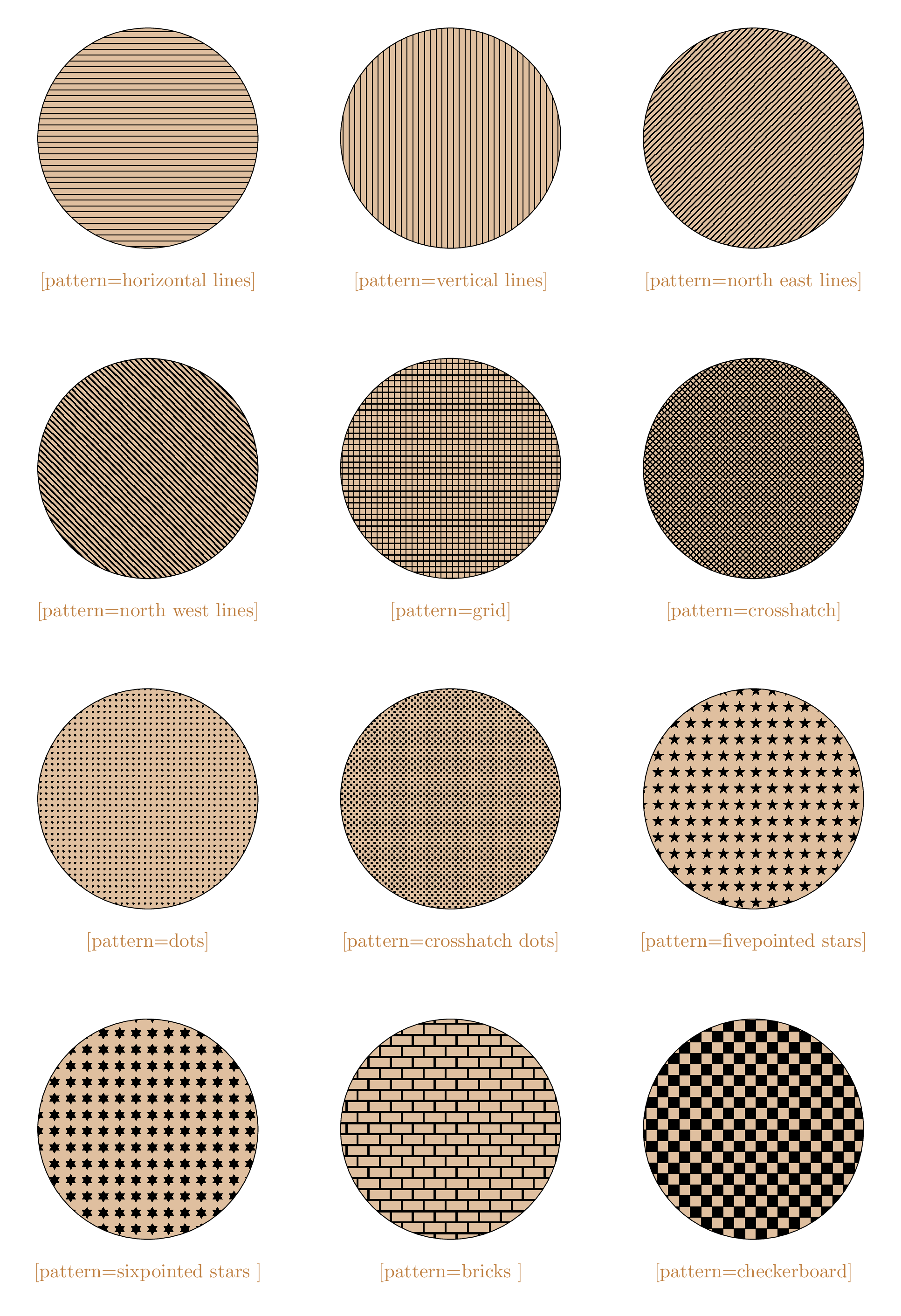
List of TikZ Patterns
Here is the corresponding code of the Pulley with supporting structure that shows how to add patterns to a given shape:
 \documentclass[border=0.5cm]{standalone}

\usepackage{tikz}
\usetikzlibrary{patterns}

\begin{document}

\begin{tikzpicture}

% Supporting structure
\fill[pattern= north west lines,] (-2.5,2.41) rectangle (2.5,2.6);
\draw(-2.5,2.41) -- (2.5,2.41);

% Pulley
\draw[fill = gray] (0,0) circle (1.5cm); % Big circle
\draw[fill=lightgray] (0,0) circle (1.3cm); % Medium circle
\draw[fill=white] (75:2.5) to[rounded corners=0.2cm] (0.2,-0.25)
to[rounded corners=0.2cm] (-0.2,-0.25) -- (105:2.5) -- cycle;
\draw[fill=darkgray] (0,0) circle (0.12cm); % Axle circle

\end{tikzpicture}

\end{document}
TikZ Node shapes: trapezium
Instead of using rectangles for the two masses, we will use trapezium shape with a small circle above it. To this end, we will load the TikZ library shapes.geometric and use trapezium as a node option. Here is the LaTeX code of the Atwood's Machine:
 \documentclass[border=0.5cm]{standalone}

\usepackage{tikz}
\usetikzlibrary{patterns, shapes.geometric}

\begin{document}

\begin{tikzpicture}

% Mass 1
\draw[thick] (1.49cm,0) -- ++(0,-5cm) node[draw=black,above=0.18cm,circle,fill=brown!70!black](cM){}
node[draw=black,trapezium,rounded corners=1pt,fill=brown!70!black,text=white, minimum height=0.7cm](M){M};

% Mass 2
\draw[thick] (-1.49cm,0) -- ++(0,-3.5cm) node[draw=black,above=0.13cm,circle,fill=brown!70!black](cm){} node[draw=black,trapezium,rounded corners=1pt,fill=brown!70!black,text=white, minimum height=0.6cm](m){m};

% Supporting structure
\fill[pattern= north west lines,] (-2.5,2.41) rectangle (2.5,2.6);
\draw(-2.5,2.41) -- (2.5,2.41);

% Pulley
\draw[fill = gray] (0,0) circle (1.5cm); % Big circle
\draw[fill=lightgray] (0,0) circle (1.3cm); % Medium circle
\draw[fill=white] (75:2.5) to[rounded corners=0.2cm] (0.2,-0.25) to[rounded corners=0.2cm] (-0.2,-0.25) -- (105:2.5) -- cycle;
\draw[fill=darkgray] (0,0) circle (0.12cm); % Axle circle

\end{tikzpicture}

\end{document}
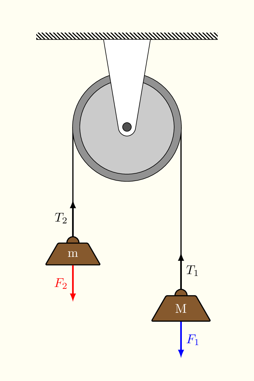
From above, the trapezium is drawn with black color, filled with 70% brown and 30% black, with white text, rounded corners and with minimum height of 0.7cm for mass M and 0.6cm for mass m.
The trapezium and circle nodes are saved as (M) and (cM) for mass M and, (m) and (cm) for mass m. We will use them to draw force arrows of the free body diagram. Check the PGF/TikZ manual for trapezium anchors.
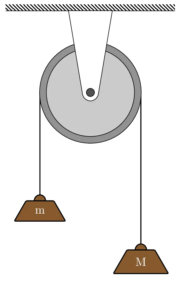
Atwood Machine in TikZ
Free Body Diagram of Atwood's machine
The free body diagram of the Atwood's Machine is shown below together with the corresponding LaTeX code:
\documentclass[border=0.5cm]{standalone}

\usepackage{tikz}
\usetikzlibrary{patterns, shapes.geometric}

\begin{document}

\begin{tikzpicture}

% Mass 1
\draw[thick] (1.49cm,0) -- ++(0,-5cm) node[draw=black,above=0.18cm,circle,fill=brown!70!black](cM){}
node[draw=black,trapezium,rounded corners=1pt,fill=brown!70!black,text=white, minimum height=0.7cm](M){M};

% Mass 2
\draw[thick] (-1.49cm,0) -- ++(0,-3.5cm) node[draw=black,above=0.13cm,circle,fill=brown!70!black](cm){} node[draw=black,trapezium,rounded corners=1pt,fill=brown!70!black,text=white, minimum height=0.6cm](m){m};

% Supporting structure
\fill[pattern= north west lines,] (-2.5,2.41) rectangle (2.5,2.6);
\draw(-2.5,2.41) -- (2.5,2.41);

% Pulley
\draw[fill = gray] (0,0) circle (1.5cm); % Big circle
\draw[fill=lightgray] (0,0) circle (1.3cm); % Medium circle
\draw[fill=white] (75:2.5) to[rounded corners=0.2cm] (0.2,-0.25)
to[rounded corners=0.2cm] (-0.2,-0.25) -- (105:2.5) -- cycle;
\draw[fill=darkgray] (0,0) circle (0.12cm); % Axle circle

% Forces
\draw [-latex,very thick,blue] (M.bottom side) -- ++(0,-1) node[midway,right]{$F_1$};
\draw [-latex,very thick,black] (cM.north) -- ++(0,1)node[midway,right]{$T_1$};

\draw [-latex,very thick,red] (m.bottom side) -- ++(0,-1)node[midway,left]{$F_2$};
\draw [-latex,very thick,black] (cm.north) -- ++(0,1)node[midway,left]{$T_2$};

\end{tikzpicture}

\end{document}
Atwood Machines TikZ Gallery
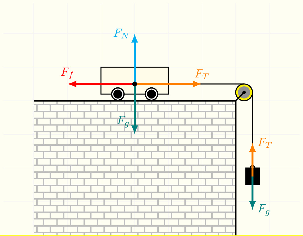
In this part, I will consider more examples of Atwood Machines. If you have any suggestions, Let me know I will recreate it and include it at the bottom of this post!
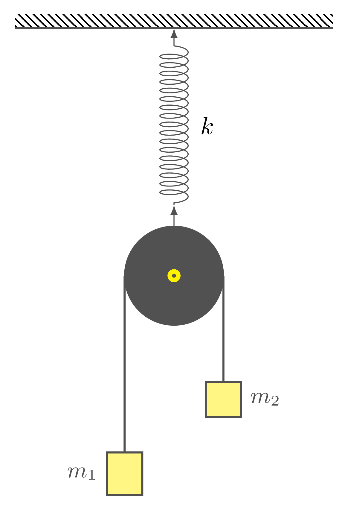
Atwood Machine + Spring in TikZ
Here is the corresponding illustration and the LaTeX code:
\documentclass[border=2mm]{standalone}
\usepackage{tikz}
\usetikzlibrary{decorations.pathmorphing,patterns}

\begin{document}

\begin{tikzpicture}[black!75]
% Supporting structure
\fill [pattern = north west lines] (-2.25,0) rectangle ++(4.5,.2);
\draw[thick] (-2.25,0) -- ++(4.5,0);

% Spring + Arrows
\draw[latex-] (0,0) -- ++(0,-0.25);
\draw[decoration={aspect=0.3, segment length=1.2mm, amplitude=2mm,coil},decorate] (0,-0.25) -- ++(0,-2.25) node[midway,right=0.25cm,black]{$k$};
\draw[latex-] (0,-2.5) -- ++(0,-0.3);


% Pulley
\draw[fill=black!75] (0,-3.5) circle(0.7cm);
\draw[fill=yellow] (0,-3.5) circle(0.1cm);
\draw[fill=black!75] (0,-3.5) circle(0.02cm);

% Mass 1
\draw[thick,fill=yellow!60] (-0.7,-3.5) -- ++(0,-2.5)
++(-0.25,-0.6) rectangle ++(0.5,0.6)
node[midway, left=0.25cm]{\small $m_1$} ;

% Mass 2
\draw[thick,fill=yellow!60] (0.7,-3.5) -- ++(0,-1.5)
++(-0.25,-0.5) rectangle ++(0.5,0.5)
node[midway, right=0.25cm]{\small $m_2$} ;

\end{tikzpicture}

\end{document}
Half Atwood Machine in TikZ
Here is the corresponding illustration and the LaTeX code:
\documentclass{standalone}
\usepackage{tikz}
\usetikzlibrary{patterns}

\begin{document}

\begin{tikzpicture}[thick]

% Background
\fill [yellow!5](-3,0) rectangle (6,7);
\draw [gray!10,thin](-2.9,0.1) grid (5.9,6.9);

% Ground
\fill[pattern=bricks,pattern color=lightgray] (-2,4) rectangle (4,0);
\draw[very thick](-2,4) -- ++(6,0) -- ++(0,-4);


% Pulley
\draw[fill=yellow] (4.25,4.25) circle(0.25);
\fill[gray] (4.25,4.25) circle(0.18);
\fill (4.25,4.25) circle(0.05);
\draw (4,4) -- (4.25,4.25);

\draw (2,4.5) -- (4.25,4.5)(4.5,4.25) -- (4.5,2)circle(2pt);

% Cart
\draw[black,fill=yellow!10] (0,4.2) rectangle (2,5);
\fill[black] (0.5,4.2) circle(0.2);
\fill[black] (1.5,4.2) circle(0.2);
\draw[white] (0.5,4.2) circle(0.15);
\draw[white] (1.5,4.2) circle(0.15);

% Mass
\draw[fill=black](4.3,2) rectangle (4.7,1.5);

% Free Body Diagram
\draw[-latex,red,ultra thick] (1,4.5) --(-1,4.5) node[above]{$F_f$};
\draw[-latex,orange,ultra thick] (1,4.5) --(3,4.5) node[above]{$F_T$};
\draw[-latex,teal,ultra thick] (1,4.5) --(1,3) node[near end,left]{$F_g$};
\draw[-latex,cyan,ultra thick] (1,4.5) --(1,6) node[left]{$F_N$};
\fill[black] (1,4.5) circle(2pt);

\draw[-latex,teal,ultra thick] (4.5,1.75) --(4.5,0.75) node[right]{$F_g$};
\draw[-latex,orange,ultra thick] (4.5,1.75) --(4.5,2.75) node[right]{$F_T$};

\end{tikzpicture}


\end{document}
